

The "SQ" Framed, BSA Otter...
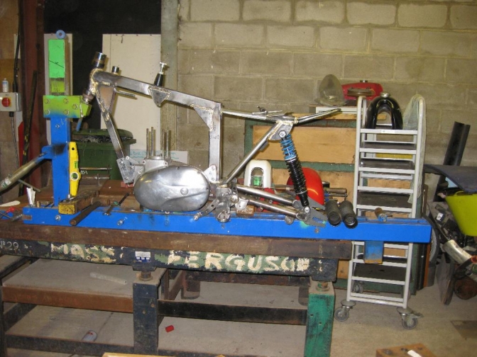
The “SQ”. Square framed "BSA Otter". Just has the looks of something, Great. ~~~~~~~ A British "Britshock" in the making!
All Photos "Otterman"© ~~~~~~~ Well it has been a while, 2011, Was when after a discussion with a friend about the cost of trials frames, and also if it was necessary to use exotic tubing in their construction? I said, from first seeing a Bright red D O T. square framed trials bike in the showroom of Eddie Dow in Banbury in the early sixties, I had one day wanted to build a square tubing framed motorbike. So this was the opportunity to try. I later on in the sixties was the first manufacturer of horse-boxes, to use this bright ERW square steel tubing. And this was firstly welded with an arc-stick welder until I had one of the first mig welders available... So I said I would build an “Otter” frame just for the exercise, and not necessarily to use for a bike... But just to see if it was a lot quicker to mig weld a frame together and get a reasonable finish, For the cost of the tubing used.
Well has soon as I started on this frame, and decided to design and build each part to be as simple as possible with the minimum of process, I started to like what I was doing.
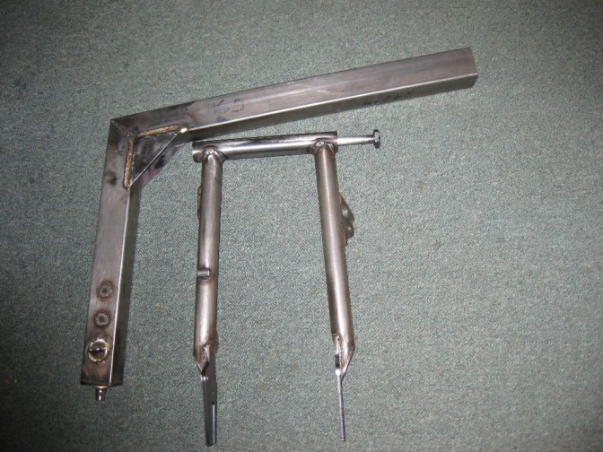
And the frame with its square sections, just helped every operation to be far quicker and more simple to build... Through frame tube spacers only needed holes drilling from flat to flat, and without the need for a centering jig, like the round-tube frames... Swinging-arm box squared up straight onto the flat surface of the seat tube...
Probably the longest job was to make the swinging arm, with its round section tube. And even this was quicker in construction being Mig welded.
Anyway you have probably looked at the Build sequences in the “Gallery”...
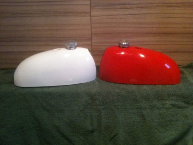
Well last month I changed the rear mudguard loop on the frame, so it was more to my liking (Top Picture) and one of my Ray Small copy fuel tanks is to be used on the build.
A couple of my Ray Small GF Copy tank's.
I just hope this frame rides as good has it looks ?
Why Now... I here you say.
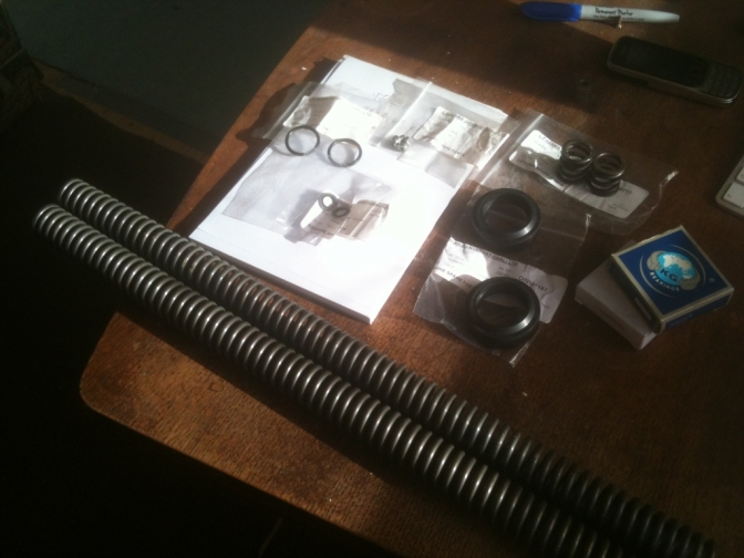
Well, after doing the page on the "Dizzy" to “F” type engine conversion, I decided to build the engine up to the same specification as the other two being rebuilt... And set too to find the rest of the parts necessary to build the engine...
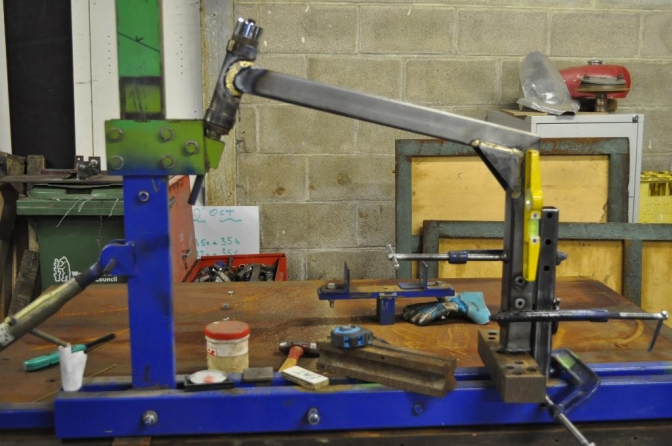
Well, I now have them apart for a distributor drive bush that it looks like I will have to make on the lathe. Triumph/BSA Four Stud forks, and Yamaha TY 250 front wheel will be used, now that I have made a batch of steering stems, spacers and brake arms for these... So Let the build begin!! PS, hope it does not take very long?
11/10/2014. OK... Has you can see from the 2014 News page I have found an engine already built up for this bike, so that we can get the build finished. I have fitted a pair of "Four-Stud" forks that I have built up using mainly new parts. A Yamaha 175/250 TY front wheel is ready to fit, although I may replace the spokes with new.
16/11/2014.
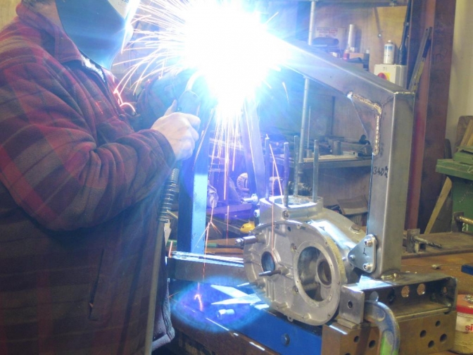
I have this week been trying to press forward with the SQ BSA “Otter”. I managed to buy a BSA B25 engine to speed the build up... Well that is what I thought...How wrong can you be... The engine unit was said to have been overhauled. And did not look too bad from the out side. With the only blemish being a repaired barrel fin, with the weld still showing. Yes I am leaving that, Why? Well it could deter a possible thief has this engine would be the only one with this repair. Anyway the engine unit was bolted into the awaiting frame. This took one afternoon for me to remember which side the spacers should go etc. well it has been a long time since I finished the frame. Well engine in, I could see that a new gearbox sprocket had been fitted. But far to high geared for a trials bike, and clutch slip to get away on a road bike with this fitted. So off came the primary chain case, trying to save the new gasket fitted has I went. The clutch was taken apart and the centre nut loosened eventually. That nut was tight, far to tight. This was going to be the story for the rest of the strip down. With my puller screwed firmly into the clutch centre and again too much pressure onto the bolt, with a smart tap the clutch was free. Now for the engine main shaft. The alternator was removed, and again with far to much pressure the nut came undone. I then had to make a puller to get the sprocket off, another half hour. With the clutch engine sprocket and chain now removed, it was time to inspect the clutch. One word “Shot” every part was worn out. And it was pointless refitting the item, especially with a new engine sprocket as well. So that was going to be a headache for a start. The gearbox sprocket inspection cover was removed and again after the need to use a drift to remove the sprocket nut that was pulled off as well. I could see a new oil seal had been fitted so the 428 x 14 tooth new replacement sprocket was loosely fitted. The clearance on the tab washer was adjusted with the bench grinder and so was the retaining nut so that the chain had clearance. Next stage was to remove the engine oil seal and spacer. This seal was new, but too wide for the smaller 18 tooth sprocket. If the engine had have been stripped, the oil seal flange on the crankcase would have been machined down with the milling machine, The oil seal was removed by drilling 3 small holes into the top of the flange to be removed and then prized out with a sharp scriber. The spacer was then removed eventually this again was tight onto the main shaft where as it should only be a push fit. I could see that a new roller bearing had been fitted... So if I was going to machine off the oil seal flange to fit the narrower seal, how was I going to stop the swarf getting into the bearing? Our old friend Plasticine modelling putty came into play, the cavity into the bearing was sealed with this and the particles of alloy to be removed would stick to this. That was the easy bit? For some reason the Dremmel had gone missing? And the only tool I had was a 12-volt version for mini modelling. So with a Dremmel cut off wheel and grinders fitted to this, a determined stint of 2 hours was spent removing the flange to the required depth. The seal was then drifted in the next day and the 18 tooth sprocket slid onto the shaft. In the meantime I had played for two days trying to get a descent manifold and carburettor line from the engine to miss the seat tube. This is OK with a BSA C15 head has the manifold veers to the left and with the engine over more this way on a trials bike you have clearance for the “Otter” down tube. But with a BSA B25 engine the manifold veers to the right and straight to the seat tube. I had a spare B25 head, and a new Mig alloy welder had arrived into the workshop, and Paul Ellis was trying it out... Well, I had done the following exercise on my other B25 engined “Otter” so I reached into the depth of my brain to remember what I had done with this head, and It soon came back to me. And within ten minuets the spare cylinder head was on the steel band saw, and the manifold removed in a straight line the same as the finning on the head. The manifold was then reversed tided up and Paul tacked it into its new position facing the left...
Go for it, I said and within 5 minuets the manifold was re-welded to the head, and with out any pre heating that you have to use with a Tig welder.
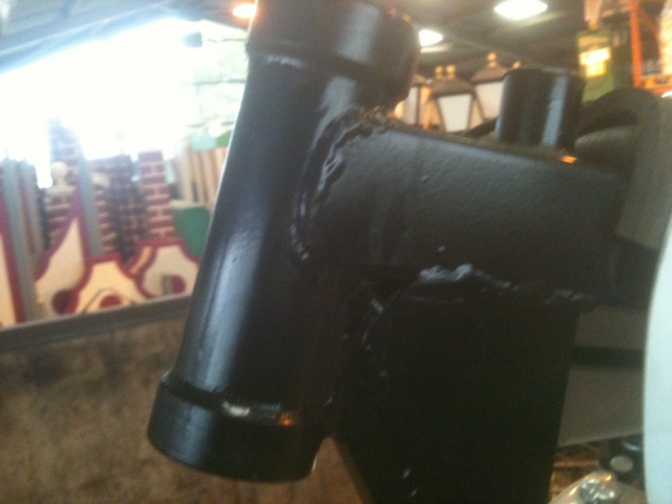
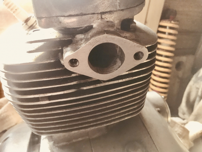
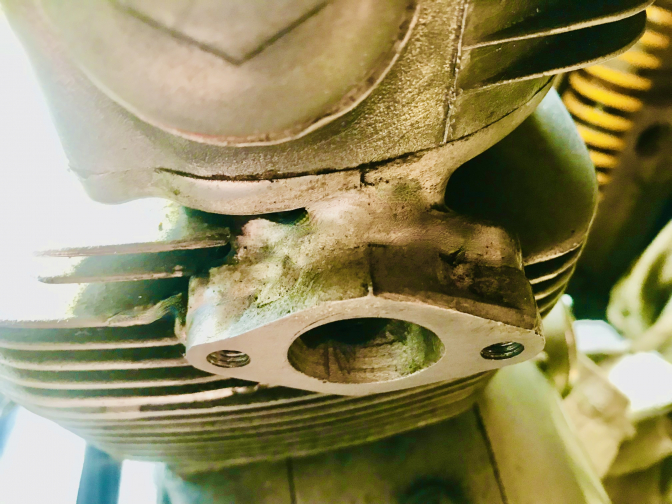
Photo of reversed Manifold...
Second photo you can see the angle better...
I spent another 15 minuets with the little Dremmel and a file tidying up the inside of the port, and the head was ready to be fitted with the valves from the head that I was about to remove... Again the head bolts had been over tightened and caused grief removing them, with the engine still in the frame... Then the barrel was removed to check that the bottom end was OK, and it looked like new rings were fitted to the piston, I spent half an hour with the Draper honing tool removing the rust marks from the barrel, there is just discolouration of the bore but the surface is good.
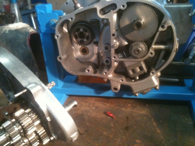
You know when you try and find the easy way to finishing a bike more quickly and then it backfires on you! Well this build has turned into that. Speed, what speed? Well with the head removed while the engine was still in the frame, and all the stubborn rocker studs removed first to allow removal of that item. I thought I better lift the barrel to check that the rings were OK. When removing it I distinctly heard a ching! as if something had dropped into the crankcases. I spent a couple of days pondering the situation, and came to the conclusion that I would have to remove the engine again from the frame, so that I could check there was nothing flouting about in the cases. The engine was blasted with the airline whilst upside down on the cleaned welding bench. I then removed the sump plate and filter. No foreign body found. But what I did find was that new gaskets had been hand cut for the sump plate and not trimmed enough, so they would have restricted the oil flow, also a amount of silicone jointing was flouting about around the gasket and filter. A definite No-No... New gaskets were fitted without the use of silicone. By this time I had my doubts set in about the rest of the engine unit. A decision was made to check on the gearbox build now has well. Stripping that side of the engine things looked all right, until I took a closer look at the gear selector shaft. This had been repaired badly with one of the repair shafts you can buy. It had been sliced half way down the shaft and the new section welded on and then been dressed with a file. Well not too bad, put fitting the shaft into the lathe to check its trueness was another matter. It was bent. I spent fifteen minutes truing the shaft with the press and then re spinning it until it was true enough. The rest of the gearbox components looked OK, and new bearings seem to have been fitted. There was again far to much silicone jointing on the case facings. After close inspection there was found to be rust ingress on the gear selector hairpin spring so this was replaced. So there we are, One-step forward two steps back. And now I have to wait until after Christmas to source the clutch components needed.
So when the New Electrex-World ignition arrives the motor can be reassembled. This has now arrived and because of the delay on the clutch parts, of this engine I have used this Electrex-World unit on the Scott Ellis BSA engine build? Yes that is on the way now too.
I also have to sort the back wheel for the bike this next week. I have a Triumph Cub rear hub, that should be widened again? But stupidly I bought some spokes from eBay, well Central Wheels actually, and hit the button before I thought! Don't do it, I have not made this mistake very often, but the price was right. And my greed, or budget took over. The spokes are for a standard hub so when you think about they will be too short for a hub that has been widened by 1 inch . We will see what happens next...
Update on the rear wheel is that I have bought another Jialing JH125L New rear wheel for this build now and spoked it into a new alloy rim, I have a blank 64 tooth alloy sprocket for this, but need to machine out the centre hole to 52mm, for a fit...
04/04/2015...
I have been back working on the SQ bike this week. I have now nearly reassembled the engine, it has been a struggle though.
This is just one of those jobs that never ever seems to go right.
Fitting the piston back on the rod was not easy, and needed both the pin holes in the piston dressed and then again the small eye on the con-rod, trouble is with me I like every thing to work as they should and not end up fitting parts with the use of a hammer. The barrel was then difficult to start over the rings, because there is no taper on the bottom of the bore. I ended up using some stucco alloy and a large jubilee clip as a ring clamp, because the clamp I have is too deep... Then to fit the new guides into the cylinder head that I had modified the (inlet tract). Heated the head up after making another tool to fit them with, and gently tapped them in.
The inlet was fine, and square, but the exhaust guide had gone too far into the head... I tapped it out slightly, and tried in the valve, but it was not square to the seat... So I called it a day, in case I did something that I may have regretted. So yesterday I tried again, This was just not going to work, so out came the guide. I could see that there was a step in the mating face of the guide seat about five mm down, this was allowing the guide to be knocked in too low. So there was only one thing for it, to make a new one off bronze guide to fit the head, the one fitted in the head before I owned it had been going up and down with the valve and acting like a planisher in the seating. This happened to me on the Triumph TR25 engine if you remember... Must have been a common fault. Anyway an hour and a bit later, I had my new custom made valve guide. And heated the head again and fitted it, the valve slid into place and sat nicely thank you, square on into the seat.
A new clutch is on the way so we should get the primary side finished next week too? More later.
04/04/2017.
Well I have the SQ BSA Otter bike in the shed at home now and all the bits are getting under my feet. And after the glorious build of the Bill Todd Special that this bike dictated the build of, it is time to get the machine built up and finished. I now have a new pair of BSA-Triumph Four-Stud forks with modified damping that I need to use on a machine to try, so this is an ideal opportunity to get them fitted to the"SQ"BSA Otter and test them out. So watch this space in the next few months, for a final build of the machine the "SQ"BSA "Otter"...
More on the build in 2023...
Updat2023...06... |
| Visitor Counter: | ||||||||
 |  |  | |  |  |  | ||