

DIY, "Otter" frame Page.
This page started in 2012...
. This is the OOTC frame I built in 2010... ~~~~~~~
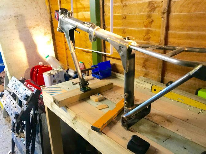
... The New Foster Otter frame built 2018...
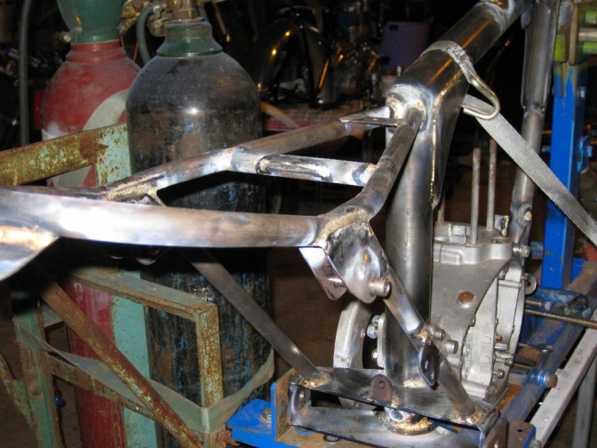
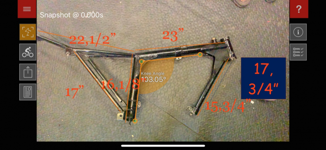
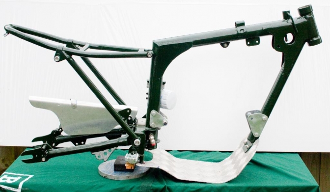
OK... For those of you who reckon you can knock up an “Otter” frame for your selves. Here is a bit of information. Things you will need, as well as being able to weld, (or have someone you know who can), is a flat steel bench, or better still an engineers facing plate (Steel Surface Table). I suppose at a pinch you could get away with a thick plywood faced bench. But you would need to check it is flat in all directions with a straight edge. You will see why you need this facility if you now look at Photo 1.
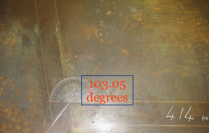
Flat bench checked for levels... Angle should read 103.05 degrees...
This has the measurements from my frame for the lengths of 2 inch seamless T45 tube. 590mm for top (tank) tube, 414 mm for seat down tube, But with the oil drain cap fitted to the bottom the measurement should read 420mm, All upward measurements are from this length.
I, as you know used T45, steel tubing 16 guage but the next frame I build is going to be out off cheaper tube. (For Square tube frame.) As you can see the mitred joint is about 103.05 degrees, as far as I can work out. It is we have just confirmed this on Foster frame 45... (Drawing later will confirm this measurement,)
~~~
Foster Frame measurements...
These are the tube measurements that Harry Foster chalked onto his old jig for memory...And I must say they all seem to work right. The 17 3/4" in the black box is the total length of the 1 1/4" front down tube. The other 15, 3/4" is to the top of the 2" engine mounting plate. 17" seat stays... 16,1/8" down(seat) tube.. And 22,1/2" total length of the cub type seat frame... Top tube length from back of the steering head to end of tube joint with seat tube is a smiging under 22 1/2"... If you have a Triumph Cub subframe you will find that if you measure that it is not that far out from the Foster frame... Fit your engine cases on the back mounting plates you have made. And then the front mounting holes will give you the angle of the front tube...With cases bolted in. If you are building a Triumph Twin. do the same operation, having made the front alloy mounting plates and bolted those to the engine first. There is only a single hole (10mm) spacer through the front down tube so you just need to line that up to fit... If you look at the "Australian built Otter Page" you will see that for the front engine mounting he used the same through bolts as the SQ Otter frame and the New Foster, but used folded steel plates, I like this idea as it seems to look neater, and I may well go to this method on future frames...
Gary's Australian BSA Otter... ~~~~~~~ "Back to the plot"This section needs making up firstly. Leave the top tube slightly longer so that you don’t run out of length of tubing when you shape (notch) the tube to fit the steering head.
This is the next item you will need. I make mine up using a 4inch length of 2" T45, 16 gauge frame tube, and then machine up the bearing carriers.(Photo of these later.) Machined to fit these bearings below... This then makes the steering head 6 inches long.
Press the lips, of these carriers, into this length of tube and then Tig weld them around, after tacking. I make mine so that the overall length of the completed steering head length is about 6" old inches. If you are just using a surface table, fit the bearing carriers after you have tacked the Four front frame tubes on this flat surface...Four yes, seat tube, top (tank) tube, steering head tube, and the front 1 1/4" engine carrying tube.. This will need spacing up to centralise this...
The "Original Foster Otter" frame uses these Timken bearings or the equivalent.
Photo 2.
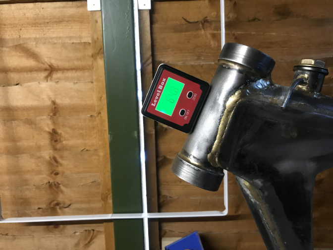
This Head-tube is set at 74 degrees and the steepest you should think of going, 60 something, would be better. You decide! 06/05/2020... I yesterday set the Foster Otter frame onto my bench to check the head angle for a frame builder, has you can see it came out at 64.8 degrees...Acute...
OK... You now need some sort of jig.
The simplest thing I can come up with for you is to clamp a vice to your bench, somehow, making sure it is square and right angles to the bench. Then get your self a length of threaded bar as thick as you can get, and make sure it is straight. You now need two cones making up, if you know someone with a metal lathe perhaps they could make them for you, alloy or steel. At a pinch you could get your Grandfather to make a couple of hardwood ones up on his woodworking lathe? (For a one off). You now need to clamp the threaded bar into the vice at the angle to the bench that you have decided for your steering head. 63-65 degrees Acute or slightly steeper is an “Otters” normal angle. But I do know that the current twinshock champions head angle is 74 degrees. 2016... So you make the choices... You will then need some way to clamp the large gun shaped frame member upright onto the bench, after you have shaped the tube to mate to the steering head. (notched) The seat tube needs to be upright, in all directions,(Plumb) before you tack the parts together. (Check it with a spirit level along with the bench). You now have a rudimentary jig, and the main frame tubes tacked into place.
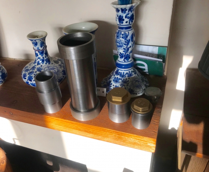
For oil carrying purposes you will now need to machine up a bung for the end of the seat tube, and I would fit a removable plug into this so that you can drain the oil. You will also need a filler cap of some description, have one turned and threaded for a Triumph Cub primary case bung is the norm, 16 threads per inch. Just below this neck you will need a tube for the oil return supply, drilled into the bottom of the top tube made out of at least 8 mm steel tubing so that a rubber or copper return pipe can be affixed. Also you will need a small 6mm vent tube set into the side of the filler neck... Or for an alternative filler neck and bung use a 1/2" BSP collar and machine that smooth to the shape I use for the Foster Otter frames and then use a brass blanking bung as a filler cap ...
... The one on the right of photo is the 1/2" BSP as used on the Foster Otters...
Back to the bottom of the seat tube! You will need an oil outlet (feed). I machine up a boss with a ¼" BSP thread in it so that you can use the new hydraulic push fittings. This outlet should be 50mm up from the bottom of the seat tube. Alternative, like the Faber and Foster frames just weld in a bend of 8mm hydraulic tube, but make sure it only reaches the centre of the seat tube so that the oil can drain down through it. ~~~~~~~ Now you have to decide how you are going to mount the rear of your engine?
If you do it the Faber way you will need two 10 or 12mm sleeve tubes, just wider than the 2” frame seat tubing with 8 mm holes drilled or machined through them... The frame needs drilling accurately for these tubes to pass through, at right angles to the line of the frame. The holes are, first 95mm up from the bottom, the second 140mm up.
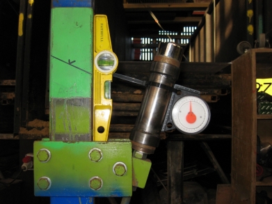
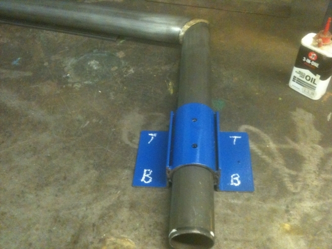
Photo Down the page with the Blue jig I use...
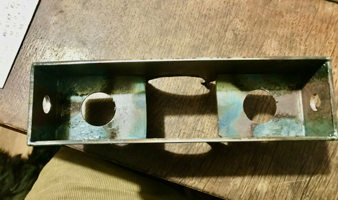
You will then need to make some small alloy mounting plates. The other alternative is to just weld on a steel mounting bracket, but you get more adjustment with the first method. Other brackets and gussets you can work out for yourself, by just looking at the photos.(in the Gallery), A swinging arm box now needs constructing. If you take a look at the pictures in the gallery you will see how I made mine. The box consists of four plates the two horizontal ones measure 9” wide. 8" Foster Otter... 75mm at the widest point that surrounds the tube and 45mm, across the pivot end, the depth is up to you but mine are nearly square (60mm down) as I bolted on separate footrest brackets. The overall width of the first measurement depends on which swinging arm you intend to use. IE, 9” for a BSA WD B40 type swinging arm. Which I reckon is the best off the shelf one to use. But you decide, but it needs to be 15-16”inches between pivot and wheel spindle. Weld this box up square, and then square it to the line of the frame before tacking in position, you can judge where it needs to sit from the photos (In The Gallery) again.
THIS is the most important part to get right though. Stick your swinging arm in and line that up to help with the final decision before welding. (String lines help). I will also leave the sub frame you use up to you. Weld on or bolt on. You know I have used a Triumph Mountain Cub one on the Scott Ellis bike (read it), and I am going to use the same on one of the next builds. (If I can find one). There are new ones from Greystones and Sammy Miller Products. ( Now Feked)
... This is the "OC"Foster frame from 2019, that I used another Triumph Mountain Cub subframe and swinging arm on. They were both NOS, the only modification was to bend up the rear of the subframe slightly for better clearance. Probably one of my favourite frames, but I always say that with each one... ~~~~~~~ OK... back to the main frame, you now need your engine, or crankcases (see Pictures again). Bolt it to the back mounting that you now have fitted to the main frame? Centralise it, and then set it over to get a good chain line with spacers. ( chain needs to run about 40 mm from the end of the box to the near side of the chain). The front frame engine mount tube now wants cutting about 485mm long. Use what diameter tube you like for this, the norm is 1 ¼" 14-16 gauge but I used bigger 1 1/2"on the Scott Ellis bike and think it is better. I may well use square section for one of the next build's, as this is more convenient for the front engine mount and stronger in its plane. Make some brackets up similar to the back mounts (Look at SQ frame!)(or the "OC" above) and use through tubes again as this way gives more adjustment. Set your engine in the position you think best. The rest is up to you. One final thing keep checking that every thing is in the position you want it, and Square, before finally welding or brazing. You will get some distortion but most can be cold set to put it right.
Any Question’s ASK. For Tube supplies look at 2015 News Page. Proformance Metals Daventry Northhants...
OK... here is a update.. 20/12/2012... After being asked what is the best tube to use on your frame, I have now found this update from Reynolds. Son Lee is well known to this company, so I will get him to contact them about tubes for your "Otter" OK.
Our Customers - Motoryclists PROJECT: DMS MOTORCYCLE FRAME PROTOTYPE - REYNOLDS 631 Reynolds "531" was used extensively in motorbike racing in the 1960-1980's. With current high-strength steels, there is an opportunity for lighter welded steel space-frames. Customer requirements Weight reduction for improved acceleration and maximum speed. Maintain the required stiffness of the frame under racing conditions Integrity of tube weld zones without cracking Fabrication using current TIG/MIG welding processes. Project solution and benefits Use of 631 tubing to replace Cr-Mo/T45 tubing Lighter tube with 800+ MPa yield strength in the weld zone.The space-frame is 19% lighter than the Cr-Mo version.TIG welded on the same jig as before, with similar diameter tubes No cost increase due to tooling Brand recognition for Reynolds 631 helps the frame-builder market the change in material and improves product margins. Leading motorcycle designers in the UK, Spain and Germany are now considering a re-design for Moto2 GP frames to take advantage of the strength improvements (without losing stiffness) using Reynolds 631, 853, 953 and with the innovative application of butted tubes on some parts of the frame. For more information on current motorcycle tubing or the CLUB 631 projects, please email petejones@reynoldstechnology.biz
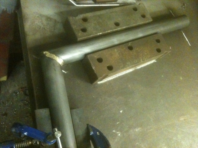
OK, 5th Dec 2014... Now I am in the process of starting another "Otter" Mk 2 frame, I thought I would update this page during the build to give you a bit more information on the way I go about it. So here is a couple of pictures to start us off.
This is the main 2 inch T45 frame tubes that I have mitred, and clamped on the scribed lines on the bench. (As at top of page) These were then bronze welded together this side first, then left to cool before welding the underside, this was again then checked. And then the top protruding section of the joint was then welded using the gas and a small amount of Mig wire? Well you can't get a good run over this part with bronze. I have Tig welded these joints in the past.
But the time you have Bronze welded on the flinch plates it seems more sense to use bronze from the start?
This second picture (above) shows the Blue jig I use to make sure the rear engine mounting plate holes are central to the tube, again the top guide holes are drilled, and a mandrel of the right size for the two holes inserted, then the frame is turned over and the other side drilled with the corresponding guide holes. These holes will be enlarged, to 12 mm using the Bridgeport, milling machine to fit the machined up spacers with 8 mm holes, when they have been turned... Steering head to top tube joint... There is still no easy way of getting a good close fit for the top-seat tube section to the steering head, If you have a milling machine you can set that up with the right sized hole saw, or use a "Joint-Jiger" like I do. The angle is only about 10 degrees but you will probably still have to finish the joint by hand to get a good fit, before welding...Foster Frame number. 45 the hole saw was set at 10 degrees and that was spot on for the jig... I still in the past tended to go the old fashioned way by using a hacksaw mini grinder and file. Once you have built one you can always make a template if you intend making another frame. Just a tube that slips over the tube you are using makes a good job, just slip it over and draw around the profile with a marker pen... It is a good idea to make up all of the plates for reinforcing and the brackets to hold various parts, before you start to assemble the frame, then they are on hand when you need them. If you are fortunate enough to have a mate with a CNC laser or water-jet even, these parts can be made easily although you will have to pay even a mate, because these machines are not cheap, and need to be kept running constantly to pay for themselves. A band saw and linisher or grinder is the next bet, or go back in time and use a hacksaw and file. One thing I will say is that any of these plates should be made from a compatible steel to the frame tubing. I know most people use what is to hand "Mild steel plate", this is all-right if that is what the frame tubing is made from, but if you have used T45 or Reynolds 631 you need the same class of steel for the plates. The general thickness for these plates are 2mm for the reinforcing plates and 3mm for anything that carries anything, IE, engine plates, and 4mm for swinging arm box. you can get away with 2mm for the top suspension mounts has these will need pressing into shape and that makes them stronger, I do mine with tooling I made for the large Fly-Press. Other parts you will need to machine or have machined are the steering head bearing carriers, through tubes, if using them and filler cap for oil, and a fuel tank mount. You could for the oil filler use a 1/2" BSP black iron straight joiner and a Brass 1/2" BSP hexagon bung, as I said above.. but it will need a vent tube welding into the side of it...
More later as I get on with the frame.
A bit of history again.
|
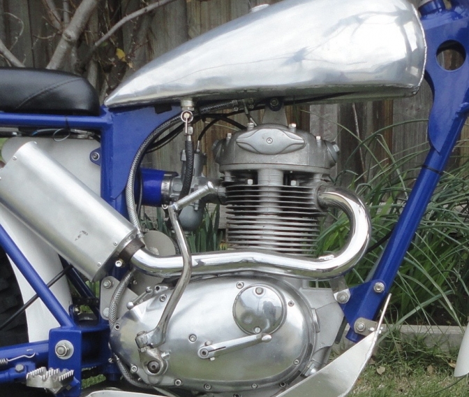
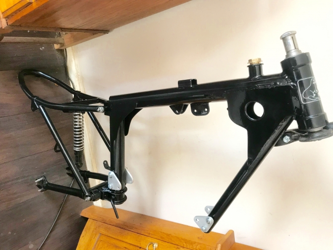
This is my Scott Ellis BSA Replica frame.
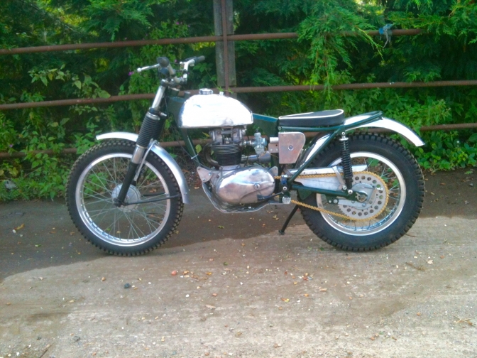
And here is the finished bike...
~~~~~~~
So this is probably the nearest to the Original frame BOK228C BSA (Except for the engine fixing plates Scott's were just weld on steel like the Foster frames...) that were copied firstly, by Harry Foster,
Harry built 43 of his frames, if I have got my homework correct.
And that also gave us the name "Otter",and then again one of the,
"Original Foster Otter frames", (Colin Dommett's)
was used as a pattern to create the Faber MK ONE "Otter" frame, of which over one hundred have been made.
Faber Update for Mk two frame. Later.
If you look at my frame you will see that I used a Triumph Cub subframe and swinging arm as Scott did with the Original.
You could always go back to doing the same if you think it would help you build a frame more easily.
I may go that way as a further exercise, with a later build. (Now done frame in above photo.)
Any questions just ask. OK...

This is my Swinging Arm jig with a "MK 2" type swinging arm in build.
This pattern was used on the "MK Two Faber Frame",
while the "MK One" and the "Foster" Original "Otter" frame were fitted with a swinging arm that was more a fabricated copy of the original "Triumph Mountain Cub" swinging arm fitted to the BOK228C original frame, but Harry had made it slightly wider for better tyre clearance.
More information on swinging arms now on the
"Swinging arm Design" page...

These rough sketches, I did from my MK One Faber"Otter" Frame and these were used as a reference when I built the "Otter-On-The-Cheap" frame.
And that bike steers and handles very well indeed.
Don't forget that The Faber MK One "Otter" frame was built with the jig taken from Colin's, "Foster Otter" frame, and the measurements were the same, including the steering head angle. Before Howard Fawkes tweaked them for the MK Two.

The biggest difference between the "Original Foster Otter" frame and the Faber frames, is the shape of the subframe top tube loop.
The Foster Frame loop was more the shape of the Triumph Mountain Cub original loop, while the Faber loop has a bigger radius at the rear, and this has put certain people off of the Faber frame, as they feel it could be tighter with the loop not as wide at the rear. But it is easier bending one bigger radius loop...

The 485mm measurement is before the back loop bend, the overall length of the subframe is 600mm, the diagonal subframe down tubes are 400-420, the chain-side tube on the "Foster"frames where flattened for the lower 80mm on the inside for better chain clearance.
Again this is not just a matter of putting a tube in the vice and pinching it up?
For a start using T45 or Reynolds 631 heat will have to be used.
again tooling needs to be made for the Fly-press or even hydraulic.
19mm tubing or 3/4" is generally used for this subframe.

The Faber version of the "Otter" also has the through tubes to carry the engine mounting plates at the rear, probably a better idea than the Original but more work to achieve a frame.
Foster frames have the welded bracket slightly wider than the engine so that adjustment with spacers can achieve the same result.
Although you can simply use a plate to cap off the bottom of the seat tube to make it oil-tight, a better bet is to turn up a bung and into this tap a central hole for a drain plug, then you have a chance to remove the crud that will form in the bottom over time.
Better still fit a magnetic Plug Bolt .
The feed oil pipe can be simply that a length of thick wall hydraulic 8mm pipe bronze welded into the seat tube at about 50mm up from the bottom. You should make sure the tube is sitting into the near centre of the seat tube internal diameter, for better oil supply.
I have machined up some small flanges with 1/4" BSP holes in the centre to take the hydraulic fitting that you can now get for the push-in connectors,
But I don't favour either method, they both have the same result to supply the engine with oil.
One thing I will say and it is on other pages is that it is a good idea to fit an in-line filter of some sort even a canister one if you find room.

OK... the above scribblings are all I had for my first "Otter" frame build,as I said, but using these measurements and setting my jig to the correct angles achieved a frame I was very proud of, as I am with all the frames I have built.
~~~~~~~
So if you feel you can give it a go, why not, you may end up with something you are very proud of too...
You can see most of the sizes etc. The tube I used was all T45 at 16 gauge.
But you could always use other tubing not even seamless if you can not afford it or you want to have a go with cheaper tube just to prove to yourself that you to can actually build a "Otter" Type trials frame.
You will have fun along with frustration at points, but the sitting on the bike with a frame you have built is Priceless.
27/05/2020...
More photos of the Foster frame to help you...

The Foster swinging arm box...
Under this box is fitted the footrest carrying plate that reinforces the structure...
But I have now added vertical webs into the box to reinforce further...

Here you can see the webs I have added ,
these will be on the Foster Otter production frames...
Now I have updated the swinging arm box for the latest Foster Otter frame to make even more rigid...Februrary 2023...

And a sketch I have sent one of the new DIY frame builders ...

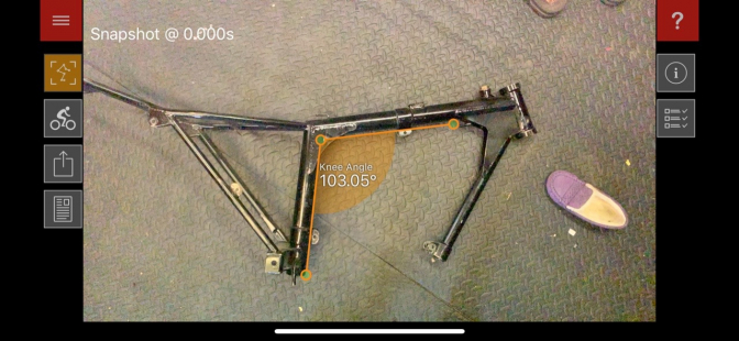
Here you can see the steering head angle on the Foster frames better
^
It is 64.8 degrees.. and the angle you need to cut with your hole saw to join the head tube to the top tube is 10 degrees...
~~~~~~~
27/06/2020...
Later this next week, I will start to prepare the parts for another Foster Otter frame.
And put each part up with information, so it will be easier to follow.
Here is the start of Peters Triumph Otter ...

2"16 gauge T45 tubing...
I have told Peter the Ariel swinging arm would have to be an inch longer.. We will see what he comes up with...
Dimensions for the Triumph Otter builds I can get from our friend Ian Ballard.. Who is building up his Foster Triumph at the moment...
More later...With Steering head details...

Bearing collars 20.84 mm wide...

Collar width 4.33 these I have made slightly thicker than the original Foster size to make them slightly stronger...

OK... this measures 50.00mm, but you turn yours to the tolerance you want to fit the 2"x 1" tapered roller bearings. used...

Outside width of the collars are 59.06 mm...

This is the 2" 16 gauge T45 tube used for the headstock (50.76 mm)...

The length of this tube you can see is 5 1/16 " long...

This makes the total length of the Foster Otter steering headstock 6" inches...
It is up to you whether you braze these or tig weld them, and it depends on if you are using a jig or a surface plate to build your frame when this operation is carried out, if you have a jig do it before you sit it onto the headstock fitments like I do, if you look. If you have a surface table, tack all four front tubes on that before fixing the collars to your head stock...
Any questions ASK...
~~~~~~~
For my next "Otter" frame, I am going to try my hand at Bronze welding using a Tungsten Inert Gas (Tig) welder instead of the Oxy-Acetylene bottles that I usually use.
Why? Well, for one thing I have always wanted to have a go with this method since I found out you could do it, but with a load of Sif Bronze No 1 rods in my possession I continued to use the Gas set.( you need Sif No32.. Or some use Sif No 101, the rods used for use with a Fluxer... I will try both.)
Now I have decided that I could use a DC current Tig welder at home and buy disposable Argon Gas canisters, This would solve the problem with the house insurance, if you have a set of gas bottles in your garage.
Yes you use A Dc current Tig, and a thorited tip, with Argon as the shielding gas, the rods to use are Sif Bronze No 32, and these are quite expensive, but I am going to bite the bullet and buy the lot a Welder for £300, ARGON disposable bottle @£34, and the rods at £94 for 1kg.
Here is a really good video that gives most of the information about TIG Bronze welding..
Thank's Tony good information...
This is welded right to left, and is quite a speedy process compared to Oxy-Acet,
You only need about 35-40 amps? for 16 gauge tube...from your Tig and this is just to heat the joints to cherry red and not to melt the steel tubing, this is the tricky bit getting this right. so you need to be comfortable holding the torch to keep the shielding gas over the joint and moving forward smoothly.
Mike Waller now TIG Bronze welds all of the frame joints on his frames...
I will get more examples of TIG Bronze welding here...
We now should try this method as it is rumoured that we may not be able to get the acetylene gas in the future...
More Later...
Updat2023...
| Visitor Counter: | ||||||||
 |  |  |  |  | | | ||