

| "Britshock", and "Otter" Tools. Used in there manufacture.
For some time I have been asked to explain some of the tools I have had to make, to build the "Otter's" I have put together.
And to explain the function of the frame jig that I constructed.
This week I was asked again to explain the tool that I made to Swage the BSA Bantam headstock to reduce it to size, to be able to fit the available 47mm tapered bearings.
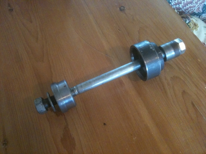
So this is the tool we will start with.
The parts for this, had taken me about three hours one afternoon to make, and complete the task of swaging of the headstock.
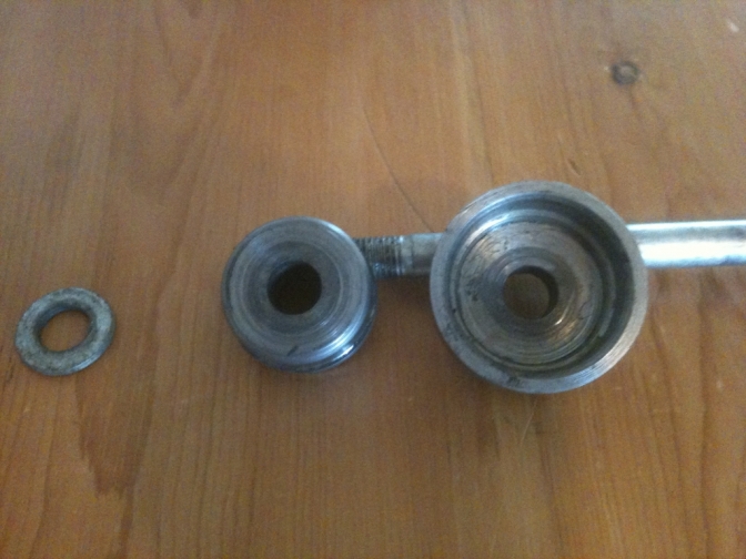
The parts were turned out of steel stock from the bin. The top female swage was actually two parts ? Top pressure plug was 50mm solid round-bar, the female tube was 2.1/4" thick-wall tube. This was machined on the internal face to just under the size of the outside of the BSA Bantam headstock, with a smooth taper entry to start onto this. The bottom male swage was also machined out of 50 mm solid bar, with as you can see a rounded lead for starting. Size? 46mm. The bolt used was a 250 mm x 16 mm HT steel...
OK ... Self explanatory really how it works ?
Bolt the two parts through the steering head with the male swage sitting inside the original bearing cup ... Pull the female swage over the other end bearing carrier cup... and this will take quite a bit of pressure, that's why you need a good bolt, and a long socket bar.... Repeat the process on the other end. This time the Male part also has a job to do by opening out the swagged end to the 46 +mm for the New bearing. (32005 25x47x15...for 4 stud forks...) I use... Yes you have to repeat this, to open out the second entry too. Use plenty of grease for this operation, or the parts will bite. It is also most nesasary to use the male swage tool to centralize the pressure bolt a large washer is no good as this will slip out of the centre position...Don't use an hammer this will only stretch the steel... Now press in the New bearings. Summing up: You could use an hydraulic press for the operation if you have one? But by doing the operation using the bolt there is no impact that you can't repair? PS: it is advisable to remove the welded lock bracket as this will stop the swage keeping the bearing cup round and will bring the bottom yoke out of line... If like a friend ... you want to use the BSA A or B or Triumph yokes you will have to open out, and not close the bearing cups on the steering head, the bearings for this conversion is L44649/L44610 imperial...inside dia 1.1/16" outside 1.98" and width 0.56...
More tools later...
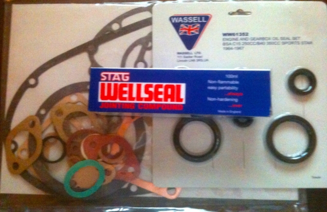
This is probably one of the most important tools in your chest? Good joints mean an oil tight motor.
You really need to make sure the surfaces on the engine covers are good. I do mine on a surface table with a large sheet of linisher belting laid onto it.
A gentle pressure onto the case being surfaced, and a figure of eight movement, for about a count of one hundred passes seems to do the trick. However, if there are deep wounds you need to keep going with the action until you have a perfect pit free surface on the joints. Work now save leaks later, is the philosophy... I used Wellseal way back, doing my apprenticeship on Fordson tractors, and still reckon it is the best jointing compound you can use? It never sets and stays flexible.
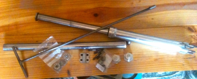
Triumph/BSA Four-Stud fork damper rod removal tool.
This two foot long tee handled rod, is what you need to hold the inside slot on the damper assembly while you loosen the Allen screw that retains the damper unit to the fork slider.
The end needs to be a fraction under half an inch wide (11 mm about) to be able to fit into the depression in the damper top, the spade for the slot needs to be about a quarter inch in depth.
I Just turned up the end section on the lathe, and drilled the hole for the handle as well on this, then hand filed the spade on the end, before welding the rod into place. This tool is a must if you have forks that have not been apart for a while and may have rust formed around the thread.
|
OK ...These are a few simple tools that will aid you if you are anticipating building your own frame, or even setting one up for any modifications ETC...
The Angle finder gauges are only cheap but being magnetic are so handy to determine any angle that you may need or be contemplating using.
A little magnetic spirit level is also a God-send to get a frame set up right for a lot of operations.
A steel rule, and G clamps, always come in handy.

Then we come to the most important tool if you are contemplating building a frame from scratch, or even modifying one.
This is my Universal frame jig.

Here is a close up of the headstock fixture...

You can see how the clamping plates can be slid up and down the the upright beam for infanite adjustment. And the beam squared or tilted with the turnscrew...

You can see that I have many fitments that just bolt or clamp between the two main base runners and can be added too when nesassary...

Swinging arm box and rear wheel spindle are secured into position to square the frame for tacking... Along with the subframe...

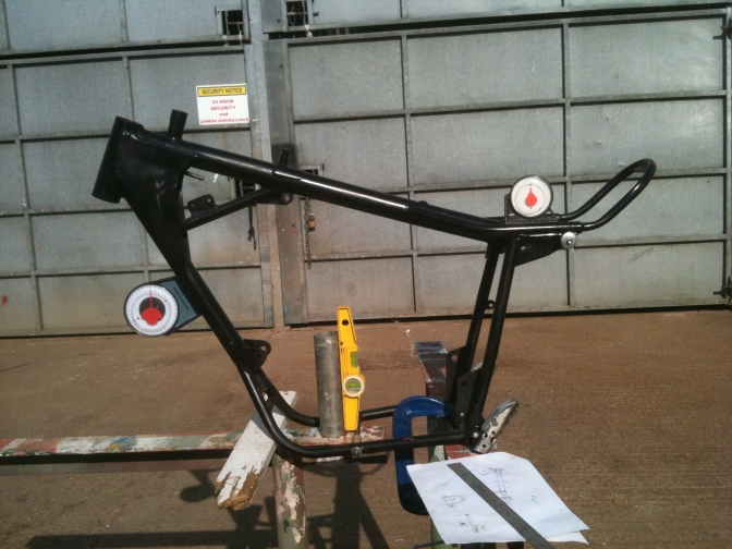
This square tubing frame was only built has an exersize, but when it was finished it was too good to not use in a motorcycle...
Note: I have the benefit of the use of the old Massey Ferguson surface table for many operations...

Not only have I built trials motorcycle frames on this jig, but I have also built a couple of cycle frames on it has well, and they have not needed much cold setting...
You also need a robust true flat surface as well, like a good steel bench or better still a surface table, even one made out of kitchen work top will suffice at a pinch for a one off...
As you can see from the photos, this jig is fully adjustable, with the steering head post being able to be moved from the upright to accommodate longer and larger frames. And any new positioning bracket can be made and then clamped, or bolted between the two large base plate tubes.
~~~~~~~
BSA Engine holding frame.

Oh, and time for a beer when a good job is done.

Yes, probably the best thing I ever made.
Just a simple frame to hold an engine in rebuild on the workbench.
It does not have to be that perfect and the bolt holes don't have to be perfectly correct as long has you can get the couple of bolts to fit through the engine bolt holes, to hold the engine secure in the frame.
Jobs on the engine are just made that much more easy and accurate, if the engine is not moving about all of the time.
A Lot more later.
~~~~~~~
I found this little video a while ago and if you are contemplating using square section tube on a build this proves you don't have to spend a fortune having the tube bent.
This is 1" tube but you could go up to 1 1/2" if you were strong enough.
The secret to bending square section tube is if you look closely at the video, you can see on the round former there is a strip of round rod around the centre of this, this can be 5/16" or 3/8" in diameter.
What this rod does is to force the top surface (Inside) of the steel tube inwards to allow the pinched metal to find a new position this will show up as a dip in the finished bend, but keeps its strength because of the new shape formed, the same will happen on the outside stretched surface but the dip will not be as deep.
Coming soon making a set of rollers to bend Square tube too.
This is Mate Paul Ellis boring one of the BSA C15 barrels on our "Olde Lathe" "Big-Bess" to except the 69 mm Triumph piston.
Paul is not only a brilliant engineer but he is also one of the UK's best "Silversmith's.
More Tools later...
And more ideas for items that can help with your bike and engine builds.
~~~~~~~

I always use an angle finder to set the angle of the rear suspension units before I weld on the mounts, because as you know altering the slope of these units does make a lot of difference to how the bike feels and performs, and it is not just spring weight and load.

A Simple jig made to hold parts in the correct position while welding is essential, as this Otter swinging arm jig made by the late Harry Foster shows.
I did not believe it would work when I first saw it, but every part was held in the correct position even down to the side stand spring retaining peg...

And the same with the Harry Foster Otter frame jig, it looked like a right "Bodge", but every bit of the BSA Otter frame clamps or bolts where it should and locates every last part... so your jig does not need to look pretty to do the job it was made too do...

And you don't need expensive tools to make parts for your frame, these wheel plates for the Foster Otter were made in the "Old Fashioned" way using a old band saw to rough them out, and the finished with files and an hacksaw, and cheap bench drill...
23/11/2025...
We are considering bending some 1960's type low level handlebars out of T316 1.6 wall stainless steel . This video has all the right bends for these bars ...
This very explanatory video is a good guide to bending these bars, and out of 22.2 T316 stainless steel makes for a good bar.
You will need for a good job one of these JD Squared Model 32 benders though and a set of 22.2 x 89CLD x 180 Dies.
Loads more later.23.8
upt2025...11...6
| Visitor Counter: | ||||||||
 |  |  |  |  | | | ||