

BSA C15 "Dizzy" Engine upgrade to side points "F" type conversion. ~~~~~~~
... If you have an Old Distributor type C15 or B40 engine and would like to convert it to a later "F" type specification? Why would you want to?
Well for one thing you can fit later gears, have a better kick-start, and clutch mechanism. And if you use points you have a better set up with more accurate timing. Not that this matters if you are running PVL or Electrex-World ignition systems, or similar. But If like Me you are trending back to the Boyer Bransden type ignition, Having the cover to fit the pick-up is a must. ______ So what do I need? The main things are a later inner and outer timing cover, side points camshaft, and as I have said a later set of gears and shafts including the kick-start mechanism. You can use the original gears if you can find a "F" type main-shaft, and will need timing side layshaft gear. No 40-3260, 3295 or for wide ratio 3299. These are not that easy to find, and I have machined up a thick spacer washer with bush fitted to fit inside the original Kick-start ratchet gear in the past , when I could not find an original.
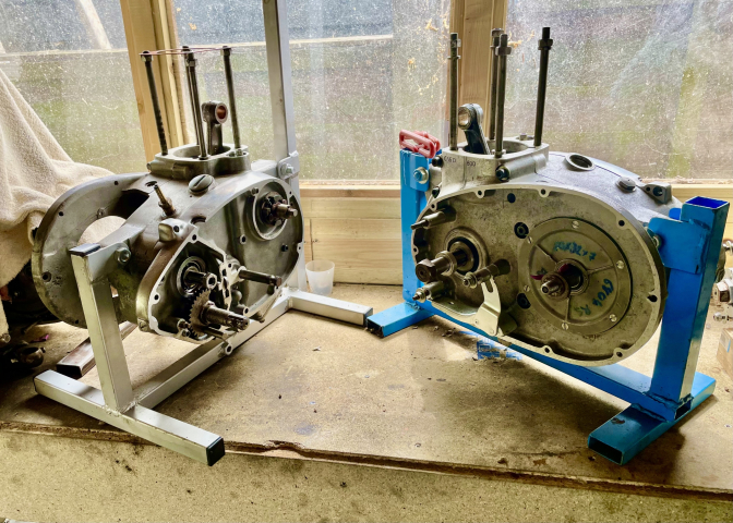
Here are some photo's, with the difference, with side covers ETC.
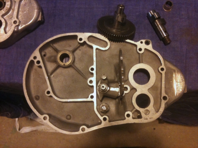
This is the original "F" Type inner timing cover with clearance for the engine main-shaft nut, Above. The one below is a later end fed case that the seal holder as been machined off to give the same clearance as the case above.
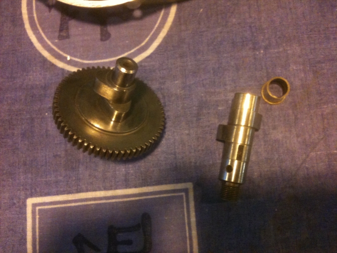
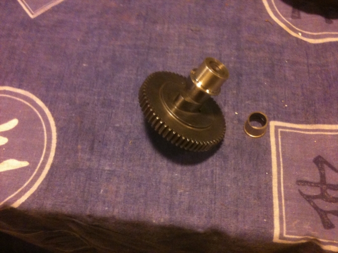
The camshaft below with gear is the "F" type to fit the 9/16" smaller inner bush. The other cam is the original Distributor model cam that fits the bigger bush.
~~~~~~~ You can use the later type cam fitted to B25's, but these need the "Big Foot" cam followers, and need the case welded up and machined with a surface these followers can run on, or a large bush with a lip machined into the case as the thrust surface.
Right... What you will have to do to fit the camshaft into the Ceefer, crankcase's, is to turn up a one off bronze bush that will fit the 9/16" camshaft and fit the larger hole in the crankcase.
Here you can see the difference in size from the original "F"type bush along side, and the new larger one sitting on the camshaft.
Other things you will have to do to the crankcase for this conversion, is to drill the threaded gearbox gear-change anchor spring pin hole out to take the plain unthreaded spigot of the "F" type anchor pin.
~~~~~~~ And also drill and tap the small hole, and insert a tapered grub screw (If not there), to tighten in the machined groove on the oil pump -distributor drive shaft bush to stop the shaft lifting...
|
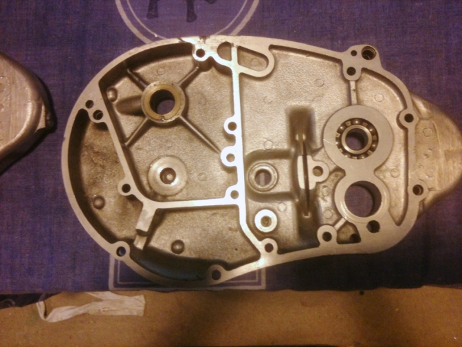
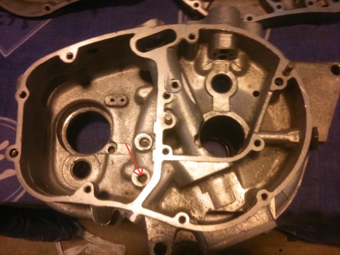
The Blue arrow shows where you need to make sure there is a grub screw present? If not drill and tap a hole to take one (2bA).
The drill bit is in the hole you need to take the threads out of...
Also don't forget when you fit the New one off bigger bush for the camshaft, you need to drill the oil hole from the crankcases through the bush top surface for its oil supply.
"This is most important."

OK... the gear on the left is the gear 40-3299 (Wide) that is specific to the "F" type gearbox.
If you can-not find one of these, you can improvise, and make up the gear on the right?
But this is only a temporary measure until you find the correct gear.
This is the kick-start gear from the Dizzie engine, and a bushed spacer that I have made up!
The inner bushed spigot of the gear needs machining down until, with the spacer fitted it is the same height as the gear next door.
The spacer now needs tack brazing into position, and the holes for the gear spigots in the rear of the gear spacer drilled to allow the selection depth of the mating gear enough movement for selection.
~~~~~~~
You will also need to machine up an alloy bung to close off the hole from the distributor drive.

This is the alloy Bung you need to knock up, to close off the distributor drive hole. It is just and interference fit (tapped in)...
You could add a breather pipe to this outlet? But don't forget that breather pipes also suck, so could suck dirt into the engine.
I tend to use a breather higher up on the push-rod inspection plate.
A really good guide to this conversion is the
"Rupert Ratio Unit Singles Manual"
This covers the bits I have probably missed out explaining.
I will update this page when I build the "Dizzy"engines up later.
~~~~~~~
OK... As if I had not got enough to do, with the builds I have?
But after doing this page just for the information!
I am now building another "F"type engine up to fit into the SQ frame.
I have a crank assembly on the way, barrel, cylinder head, and all parts to make the engine into a "F"type.
I just fancy fitting an inexpensive clutch onto this bike, but I am still doing the homework at the moment?
Just going to make a five plate up from the parts I have.
~~~~~~~
Well this bike seems to want to throw its self together does it not.
The frame was only an experiment, but then seemed too good to not use as a trials bike.
I have some experimental Triumph- BSA Four Stud forks that are going on, Yamaha TY front wheel,
and yokes.
What this bike will become is a typical British "Britshock" machine. or BSA"Otter" of the future?
I thought it best to now build this engine into has good as it gets "Dizzy" to "F Type"engine.
So now have a timing side bearing conversion from the "Good Guy's" at Dudley, Alpha Bearings, to fit, along with the steel competition crankshaft assembly.
(Sadly Alpha Bearings are now closed.)

I also have a superior oil pump in the throws of manufacture, and may fit this to the engine...

This engine is about to be fitted to the bike at last. It has been little things that have just not turned up on the ebay auction site like they used to...
The Motto is don't throw anything away any-more because someone will need it.
So has I always say, more later and pictures of the engine assembly.
21/12/2017.
I have after all this time just managed to get a pair of the correct type cam-followers.
There where some before up for sale but I refused to pay the astronomical price they were asking.
I had other work as you know this year so I was not desperate for the items.
But sadly with fewer BSA C15 spares, now becoming available, the prices have risen because of scarcity.
~~~~~~~
For me.~Oo>
You need a set of 1mm oversize piston rings,
and a gudgeon pin, and cir-clips, Tick*
a rocker oil feed pipe.
a pair of phosphor bronze valve guides. Tick*
Gearbox sprocket,Tick*, engine sprocket (small 18 tooth)On Order*
primary chain adjuster. Making own type*
Now running Boyer-Bransdon on this engine.

Photo Courtesy Trialsbits.
~~~~~~~
09/01/2018.
Victor Gear Conversion.
This last week, I decided to build up the other spare "Dizzy" crankcases and bits into an engine, to try some ideas, a friend of mine and I have, to make up an ignition system that is not the current run of the mill PVL or Electrex-World, type that we feel could be bettered at a cheaper price, using components that are available.
I am doing a page on this subject shortly.
So what I was short of for this engine build was gears.
I managed to buy a set of Victor gears last week,
and then because I could not find selector forks to buy on their own, bought another complete Victor type gearbox.
Now for the problem that I know existed because I played with the issue last year, before buying a pair of wide ratio new First gears, so that I had a pair of gears to use on my "F"type shafts I had in stock.
So this solved the problem with the two converted engines.
And I had a set of gears for my "G"type build, I am doing for the New Foster Otter.
The problem is the lay-shaft clutch side Bush/Bearing.
From the G type engine, the crankcases were completely different in that they now have a needle roller bearing (BA.108.ZOH) for the lay-shaft to run in instead of the top hat bronze bush fitted to the earlier engines.
Last year I drilled out a bronze bush to the dimensions of the needle bearing and hoped this would then fit.
But it is not that simple I found out, yes the shaft would run fine in that set up, but the problem is that the Victor gears are wider, and lay-shaft Top gear has also a "D" type spacer that makes the problem worse.
Photo.
So the complete lay-shaft cluster protrudes above the joint of the inner timing cover.

I tried solving this by fitting a gasket onto this joint, but it was one of those clutching at straws moments.
And you knew to overcome the problem there would be some work to do.
How do we start then.
Well the hole the lay-shaft bush fits into, needs a flat machining into that crankcase to a depth of just over 1mm, Calculations B25 cases 14.62 mm C15 15.87 mm.
This is to the bottom of the lay-shaft bearing (bush) seat.
This is about the recess depth of the top hat seat, so the bush locating pin you can see, needs removing, and then the area of the larger circle needs machining down to this level.
Pictures with arrows later.

So with this done we have created the same depth as the later crankcases,
Below.

Now we need to improvise on the bearing situation.
I have come up with two alternatives.
We either machine up a closed ended bronze bush to sit into the original hole, and this would now need loctite'ing in, or we could drill or ream out the hole to the dimensions of the Needle roller bearing 13/16"and if we could get a closed cap bearing, (BAM108) closed cap....Dimensions Inside dia 5/8" 15.88.mm Outside 13/16",20.64 mm. Width 1/2" 12.70,mm. £5.75...even better.
Using just a closed cup bearing we need to make up a sealing bung and fit this into the clutch side end of this lay-shaft hole, with the closed cap bearing this bung is not really necessary.
I ended up making a new bronze bush, but you could just use the old one that was reamed out to take the Victor shaft , and refit that...
So we will see how it tuns out.
Why bother I hear you say why not build a later engine ?
Can you buy a end feed crank in good condition at the right price? Can you?
Now is fast becoming the time to use what you have, I fear.

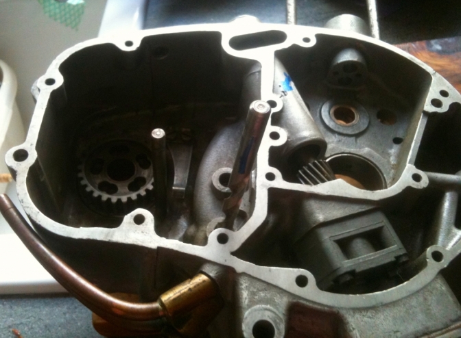
So Here is a photo to get your mind stirred.
Or "What do I do Now"?
In the picture are the components needed to convert the engine.
The Camshaft is the one fitted to the "F"type engine, and has we have said needs the New bigger bush fitted into the crankcase side to make this fit the "Dizzy" motor.......
That is that bush on the camshaft.
But yesterday I popped into the engine, a later camshaft from the B25, straight in.
But you remember, to use this camshaft we need the big foot cam followers, and a bit more welding and machining.
But I am using a shaved B25 barrel on this engine and the piston!
So option "A" or "B"?
In the foreground of the photo are the modified (Bored out) top hat bronze bush for the gearbox. Lay-shaft and next to it is the alternative needle roller bearing.
To use the top hat bush I need to machine down the 1mm stated above, and then if there is enough depth machine 2mm extra down the 23.26mm width of the thrust washer part of the top hat?
Or I bore out the bush hole to take the needle roller bearing, or the closed end alternative?
Next I have two options regarding the timing-side main bush.
Do I fit the one in the photo that is as new and was taken out to do the Alpha bearing conversion, on one of the other engines.
Or if you look there is a K32X38X20 needle roller cage bearing, that is the same as the Alpha conversion.

I used one of these to do our own timing side conversion.
We started with a similar bush and bearing sleeve the same as in the picture.
I then got Paul Ellis to surface grind the two parts (with the bronze bearing removed) to
Fit the needle roller bearing.
Then the inner sleeve needs metal taking of both sides to bring it down to the 20mm width of the bearing.
I then machined in my case two bronze spacer washers up, to bring the 26.255 width of the original bush sleeve, and to seal the ends..
These washers need to sit the width of the 38mm needle roller bearing to seal the cavity and help the oil flow to the big end.
One has to be fitted before the sleeve on the crankshaft, and the other timing cover side behind the oil pump worm drive.
So is all this worth it for a trials bike, that is going to get very little use?
~~~~~~~
If you read the next page to this "F"type duplicated, you will see that I have now bought another pair of crankcases, and this had a "as new" solid bronze timing-side bush, so job solved at the moment. but I would like to do another of our timing-side conversions.
More later as ever.
12/01/2022...
Freeola had a crash out day yesterday so I was not able to do any updating...
I was frutrated and looked on Trials Central, something I very seldom do now-a-days...
But the Gods were at home for a certain chap named Trev from New Zealand...
He had just left a New on the day post about gearbox oil-seals and had finished with the lines 'I hope Charlie Prescott drops bye.'..
Well I did, what a fluke, still can't believe it"...
I thought I must try and put some input into this post, as "God" has asked me for help... Don't knock it... you never know...
So the problem for "Bashplate" is that he has a B50 engined trials bike but the crankcases are B40. He is running a 11 tooth gearbox sprocket, and I have a feeling that has probably caused the problems.
I said that I always fit a 2mm spacer before the sprocket if it is this small as the chain usally modifies the crankcases where the seal fits.
He says the seal spins in the housing, well the original size of the oil seal was 40x52x7mm. But the later seal with the retaining circlip was bigger on the OD at 52.4 mm. And some were fitted with this bigger seal with no circlip groove machined. He then said that the ID that runs on the sprocket flat is only 37mm...
Well I have not taken a new sprocket off of an engine to check, but I think all of the sprockets that I have bought measure 40 mm across this area...But it could be a pattern part problem...
So solving the problem... I said that I just fit sealed bearings and even leave the inner facing seal in, for a trials bike makes sense to me.. The gearbox seal then is just a muck and dust seal...
I think the seal spinning around with the sprocket has milled the hole out to the 53 mm that it now measures.
Cure: well I have found that you can get a 37x53x7mm rotary shaft seal off the shelf here...But in New Zealand big question but you would think so....
37x53x7mm Nitrile Rubber Rotary Shaft Oil Seal with Garter Spring R23 / TC
£6.46 ex VAT
Lower Prices
the more you buy
Click Here…
Add to Cart
In Stock
Add to a Save List
Brand / Quality: Simply NBR Seals - High Quality
Inside Diameter: 37mm
Outside Diameter: 53mm
Width: 7mm
...
updat2023...07...
| Visitor Counter: | ||||||||
 | |  |  |  |  | | ||