

"Mini-Otter"® SuperCub,
 Number Two...
The Start Of My Second "Mini-Otter"® Super-Cub, Trials Project.
In Sequenced photo's.
This will be the complete build of this "Mini-Otter",
With all details of the build...
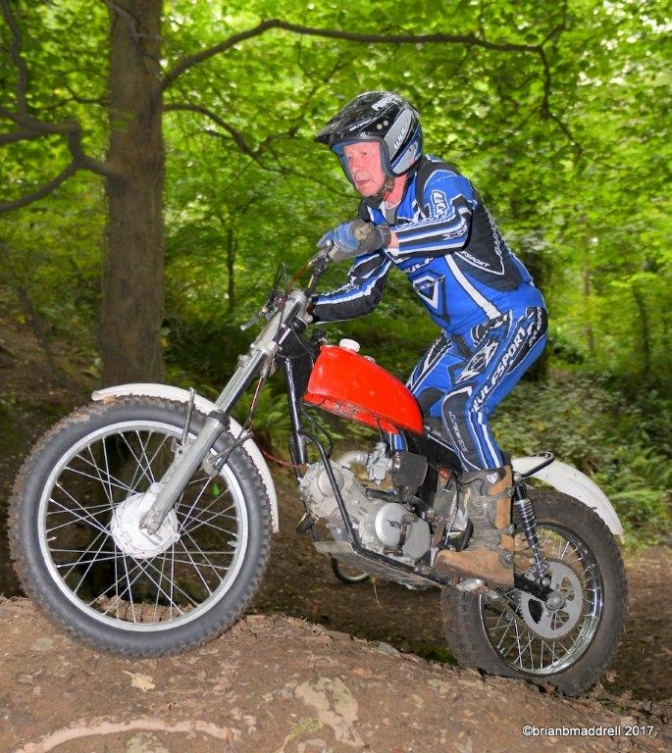
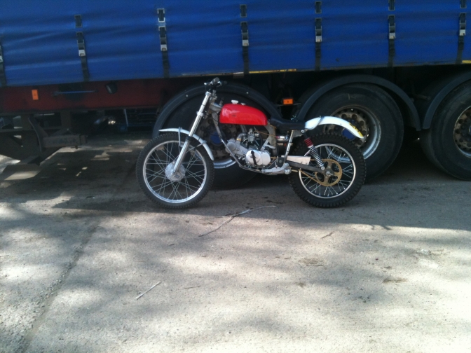
Photo Courtesy Brian Maddrell.
Brian Bedford riding the development machine in the Isle-Of-Man.
~~~~~~~
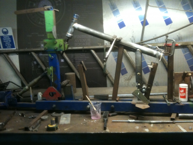
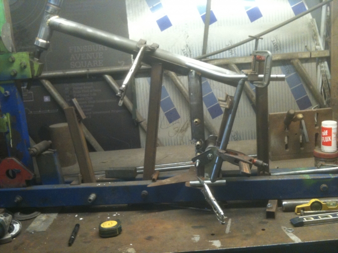
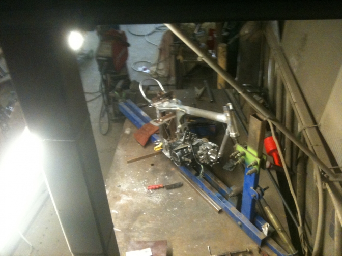
Frame first...
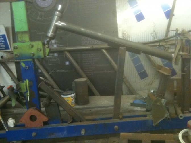
OK... not a very good picture but we have a start of the project.
All of the parts to the frame, and the patterns you will need.
I may get these parts laser cut so that they will be in stock if you are interested?
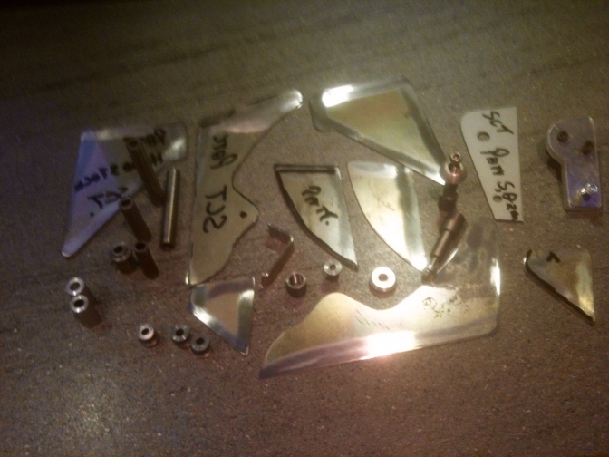
If you make these parts yourself you will need about two full days work and the use of a steel band saw, linisher, and lathe.
~~~~~~~
15/08/2017.
These are now the photos of the second build,
in sequence, so you can get an idea of the time and work put into this frame. Firstly you need to cut the two main 2" tubes to length, and also notch them to get the right angles, 5 degrees for the steering head, and 56.1/2 degrees for the top of seat tube. This then brings it to the 113 degrees angle for this joint...
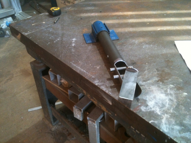
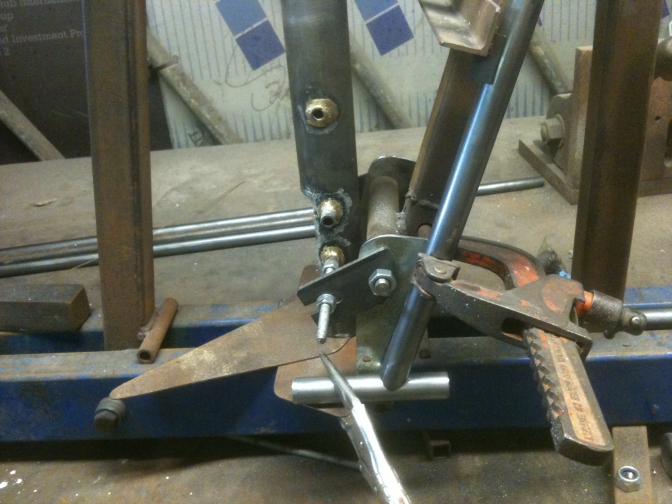
Seat tube construction.
.
The holes were drilled using the Blue jig, so that they were centred. There are other ways of doing this but this is what I used at the time, and dont forget to set the notched end to be upright off of the bench.
.
Here are the measurements for the holes, and the length to the top tube.
Taken from the first frame. 57mm up from the bottom to first tube them 45mm to the next up then 86mm to the top hanger tube... the bottom engine mounting tubes are 18mm out on the right hand side 15 mm out on the left... and the 260 mm is the length of the seat tube...
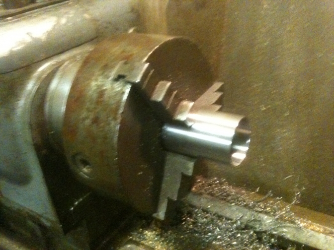
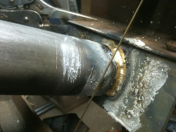
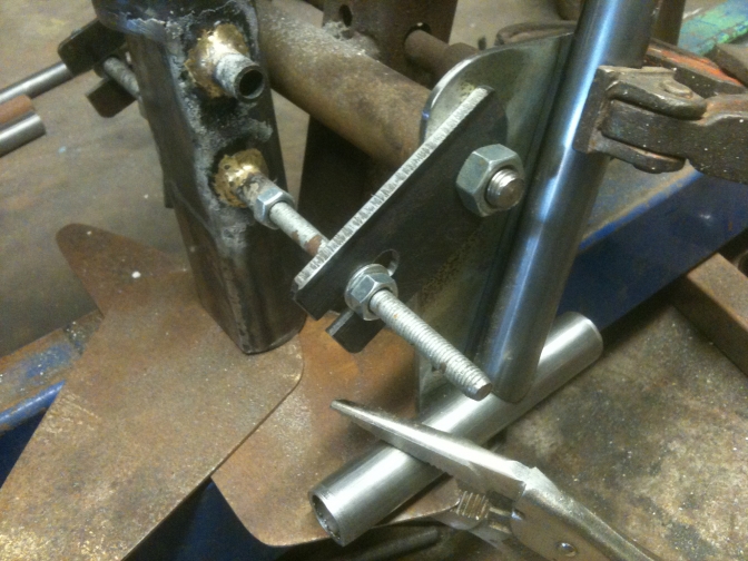
The through frame mounting tubes were turned down from their original 14mm to 12 mm, except for the 18mm that protrudes from the left-hand side, these were then dropped into the 12mm holes ready for Bronze welding.
The flat section I gas welded into the tube before bronze welding the through tubes.
The upper engine mounting tube is 54 mm long, just enough to get a build of sif-bronze around it for a good joint........
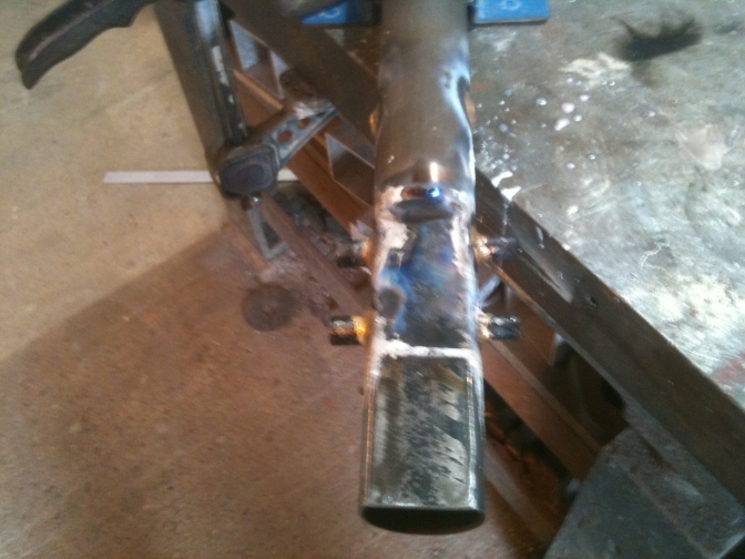
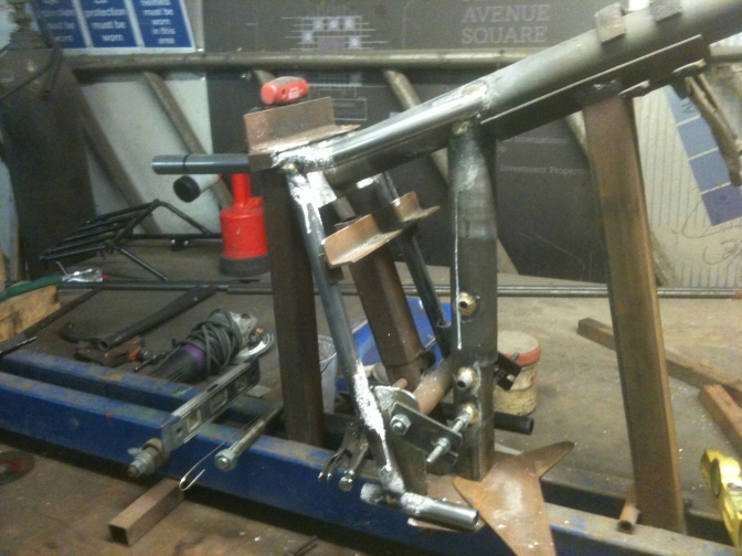
Tube now ready for the frame jig.
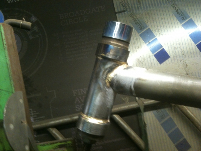
So next I cleaned up and faced the steering head tube on the lathe.
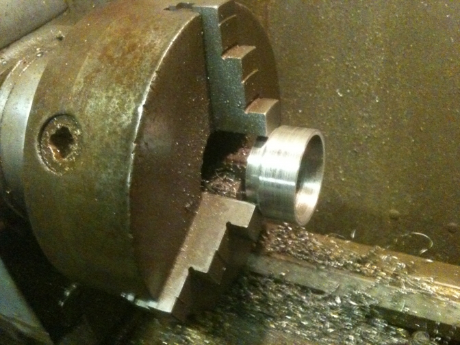
Then the bearing retaining cups.
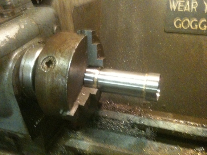
Then I bronze welded the cups to the tube, using a new jig I had made, and then cleaned the head tube up before setting it in the jig for bronze welding to the frame tubes.
Now tack bronze welded to the main frame.
And also the seat tube and subframe plate.
More of a update tomorrow.
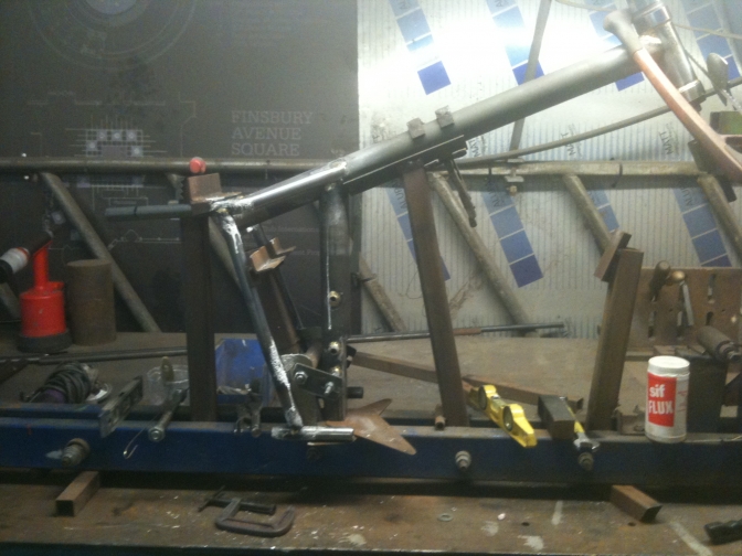
This is the next stage on from the top picture, but before any of the gusset plate's ETC, have been attached.
I upgraded to 7/8"16 guage tubing for the subframe, and seat tubes, this is the same as the "Hubbo" Mike Mill's frame, and seems a better choice for the same weight...
I have brought the engine carrying tube forward on this frame by
8mm.
Just for better swinging arm clearance.
The same 7/8" tubing is used for the seat tubes.
Using this size of tubing brings it in-line with the Mike Mills "Legend" frames.
The same size tubing is used for the rear bottom seat tube mounting, this will give more support, for the footrest, and give more room for attaching the brake pedal plates.
So I turned the jig around, and then duplicated what I had done on the other side.
I then centre'd the seat tube ready for welding in the bottom brace tube.
Both seat tubes now fitted ready for suspension mounts.
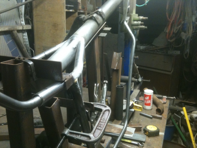
So now ready for mudguard loop and bottom brace today.
4 1/4"...
Yes 4 1/4" was right for the length from the back of the seat tube upright, to the end of the horizontal top seat tube to the beginning of the smaller section mudguard loop tube.
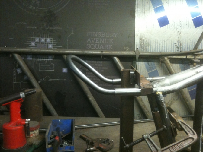
The mudguard loop ended with me having to make new tooling to bend that loop, but it came out better than the "Hubbo" original in the end, but could be better still if a proper jig was made.
The tubes now fit the jig better than the "Hubbo" frame that was used as a pattern to make most of the jig.
The bottom seat post securing cross tube took an hour to set up to how I wanted it.
Then I realised that after measuring the "Hubbo" frame again, that the measurements were right in the first place.
The seat tube itself needs squaring to the line of the swinging arm pivot spindle, to make sure the engine mounting holes are to the same parallel. You should have this right if you notched the seat tube into the top tube right. By the way, this should have been notched at
56 1/2 degrees on your notcher to get the right 113 degrees angle for this main joint...
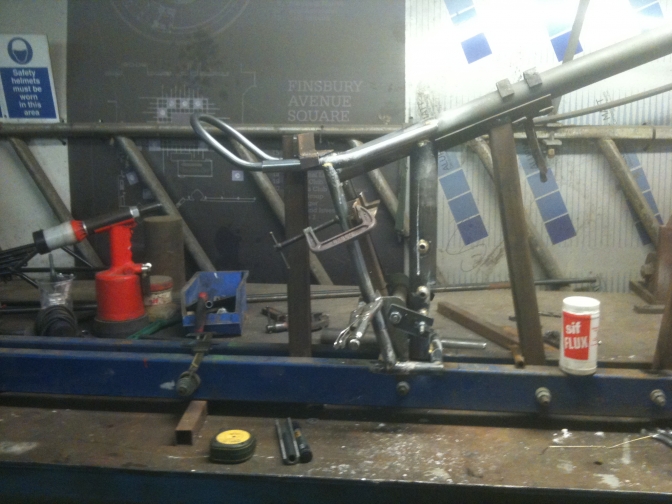
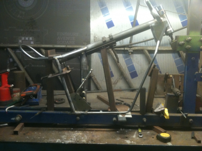
So the frame looks good so far, with a better fixing for the footrests and the seat loop looks right, it just remains to redesign the twin front down tubes to miss the engine cylinder head, but we will start that operation tomorrow, and I may not get it right at the first attempt now I have sacked "CAD" for a good eye.(eyecrometor)...
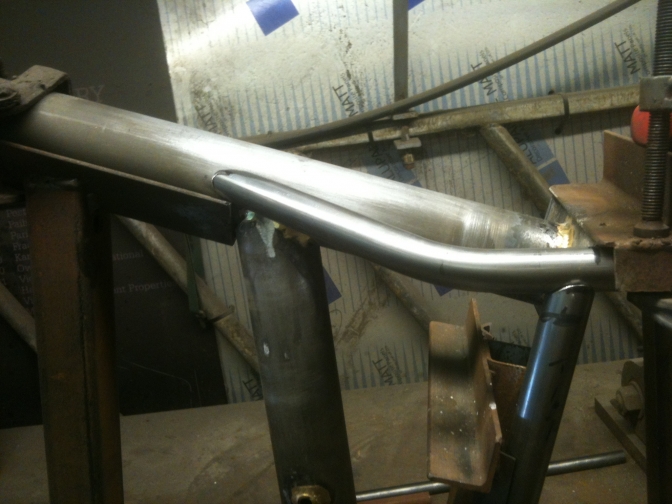
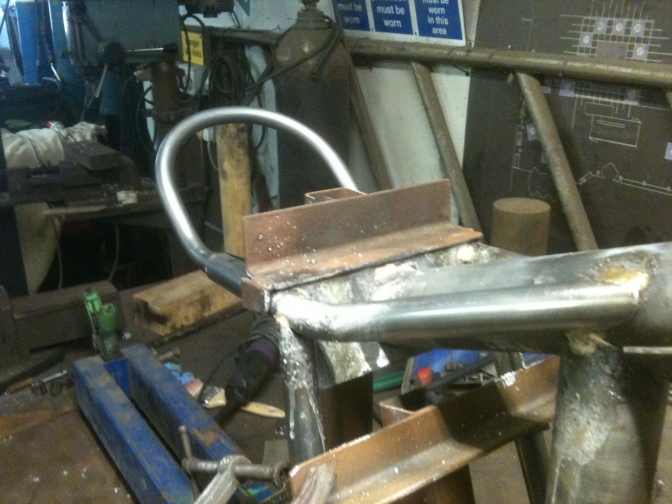
Sunday saw me bending the offside frame loop, and I thought it looked right, but was hesitant to tack weld it in place?
I took some photo's, and left for home.
When I looked at the photo's I was glad I did not weld the tube in, It may look OK... to you, but my thinking was, do I really need under-run tubes?
The tube looks good I must say, but will it restrict the steering lock and it needs to be 9" wide to miss the cylinder-head...
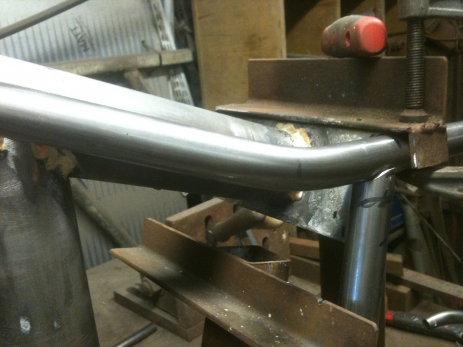
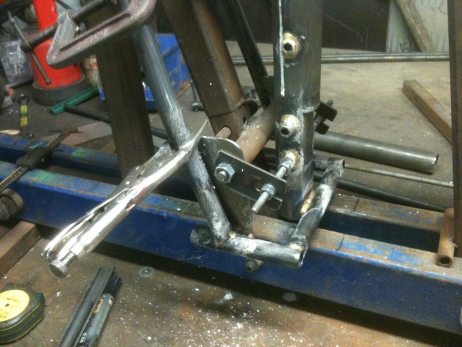
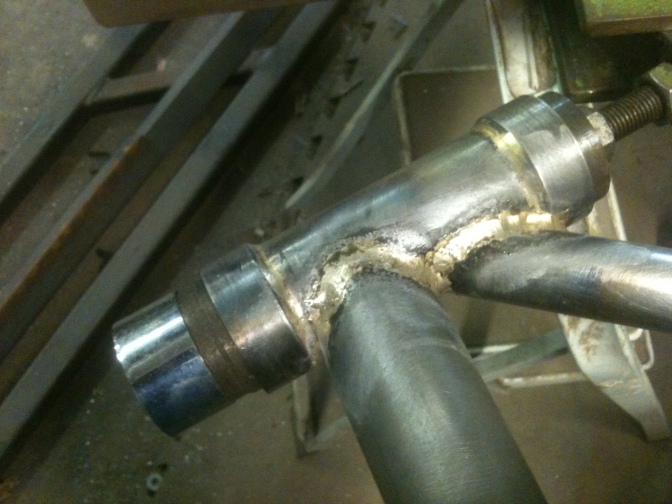
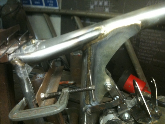
So Monday 21st August/2017... saw me make it into a proper
"Mini-Otter"...
configuration, by fitting a short front down tube of 1 1/4" T45 tubing and making up a through tube to bolt a engine mounting too, I intend to construct a structural tube and Alloy sump plate to take the bottom mountings, and end with a front mounting to connect to the front down tube fixing.
Why not just connect to the four cylinder head bolts I hear you say?
Well I could, and have thought about it, but this part of the engine is not really structural is it! And the rigid mounting may cause problems.
So What, is the other thinking, the bits for the motor are cheap why not try it and see what happens? Well I may do, time will tell.
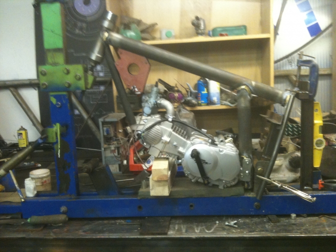
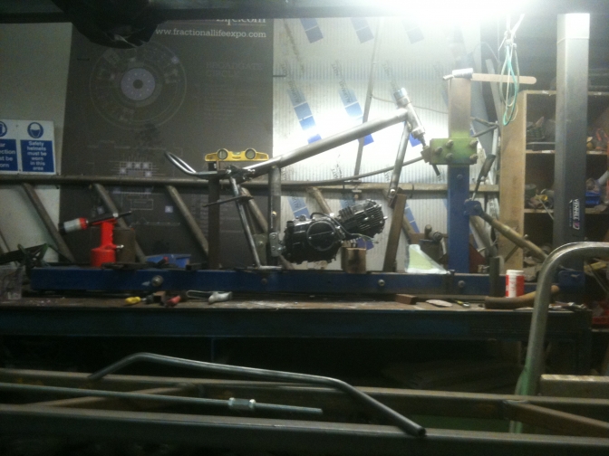
This is the spare engine for me to play with, the other NEW YX 140cc motor is going into this bike.
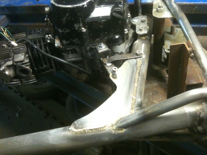
So with the engine now mounted into the frame with the top mount that I made up, the front down tube did not look right.
So I made up a new jig tube for mounting the front tube on, to get it right.
And then I tacked it and bronze welded the lot of the nearside with the jig pulled over to horizontal.
While it was like this I made up two spacer collars on the lathe for the seat tube mudguard loop and bronze welded that too.... A better day after one forward two back for the last week.
24/08/2017.
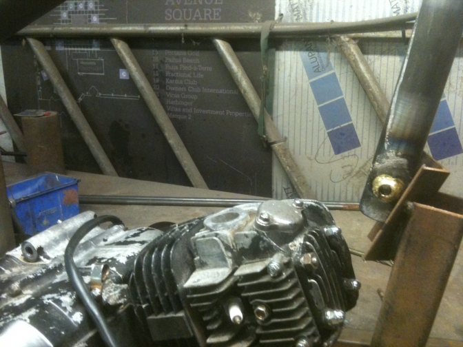
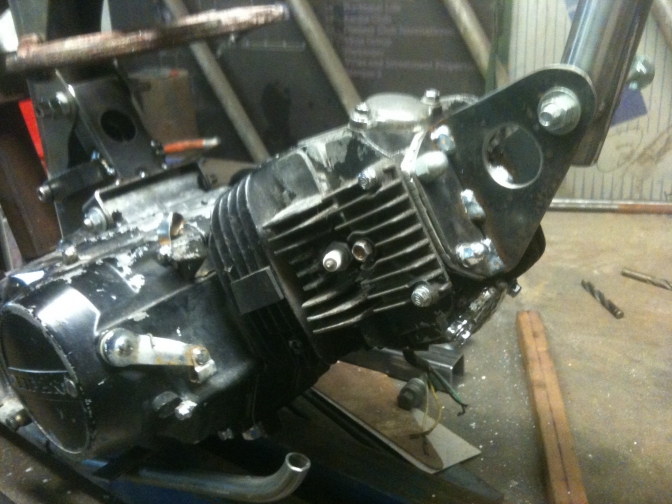
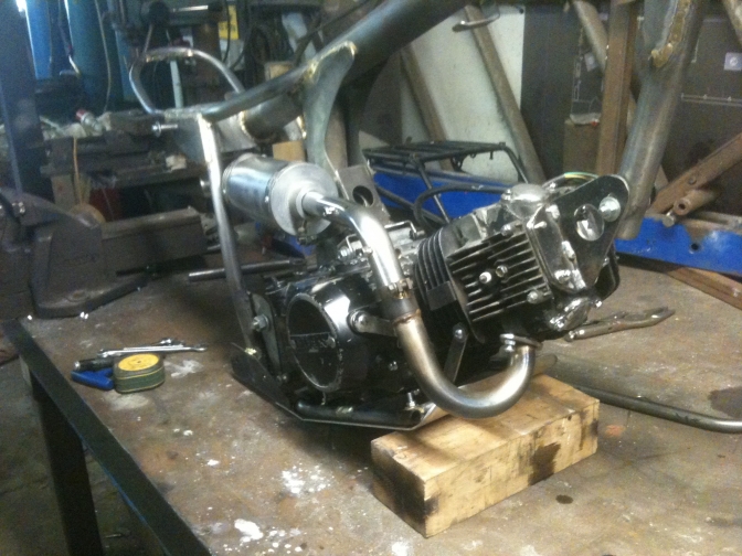
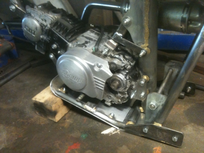
So Thursday, I decided to go the ,"lets do the cylinder head attachment route", still dont know if I am right.?
I looked beyond the "Trees" and removed the cylinder head studs and the rocker cover, and this is what it is.
I then fabricated a new 2mm steel cover and then a tread plate alloy spacer to go underneath this. Tread Plate? Well there is an air gap underneath the steel plate to dissipate some of the heat.
So then new steel 2mm flange attachments were made and tig welded to the steel plate.
And you can see, it turned out to be a good job.
I then started the under engine attachment that will be part of the sump shield assembly.
So not a bad day...
I may try this little motor in the bike before fitting one of the New engines I have.
Or may build another frame for it?
Yesterday I finally got round to bronze welding some of the joints.
A good tip is to not think,"Well I can weld this joint".
Don't until you have tacked the lot together and made sure you have everything right...
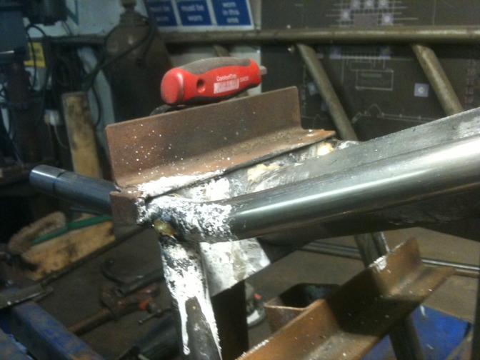
I finished welding the seat tube around the top before welding in the engine mounting plates, and as you can see left the frame in the jig, and manoeuvred that about.
The headstock joints were also fillet welded making sure it was a complete job, has don't forget the fuel is carried in this top tube.
The hole for the filler will be drilled before finishing the back joint, so that the air in the tube can escape, otherwise it will blow back and spoil the weld...
Days work complete and bench tided for tomorrow.
I have kept as you can see, most of the tubes used straight, the seat tube although they look complicated, are only one slight bend with a plumbers bender, and the two subframe tubes hardly need bending at all just a touch with the same bender.
The seat loop made of the 11/16"ERW tube was just pulled around a 5" former bolted to the face surface table, and then the two bends again done with the plumbers bender, and this was the hardest part to get right, to get the two bends the same.
If anymore frames are built I will make a proper jig for this operation or get them bent by "Tube-Bender"company at Rugby.
Note: The main tubes are in T45 tubing, but the seat tubes are just ERW mild steel on this frame so that they could be bent more easily, and the frame was for my own use...
Anymore frames and I would revert back to using the T45 as on the first frame and the same 3/4"size tubing has that.
I am told Colin Seeley used all ERW tubing on his Honda-Seeley trials bike frames though?
I played with the sump shield as well, but It just did not look right so I am now going to use a alloy plate right through, this will need a couple of alloy welded joints though, but these could also be bolted.
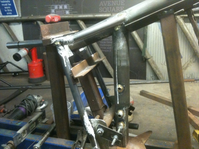
OK... here we are at the end of play on Sunday 27/08/17...
I have finished welding all joints, and fitted the gusset flinch plates. I have also decided on bolt-on footrests, so have welded on plates to except these, if these don't work right, I will again revert back to the original weld on pegs.
I have finished the bash plate, photo's later, and we will see where we get to today.
I had also come to a decision not to put fuel in the frame to keep the thing more simple, but in the end have decided that it was stupid not to take advantage of using the top tube, then any type of cover could be used, and now Brian has designed an air-box to be fitted within the
Ray Small Glass Fibre tank moulding , it needs the fuel in the top tube.
~~~~~~~
I had been looking at one of my GF tanks and decided just to fit one of these, and the lay up would just be in polyester resin? Well I am using ASPEN fuel in these little bikes, so there would have been no problems.
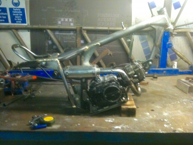
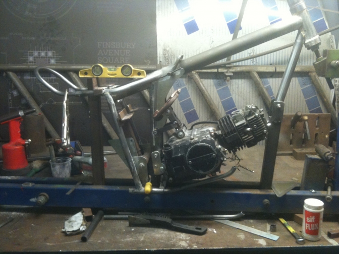
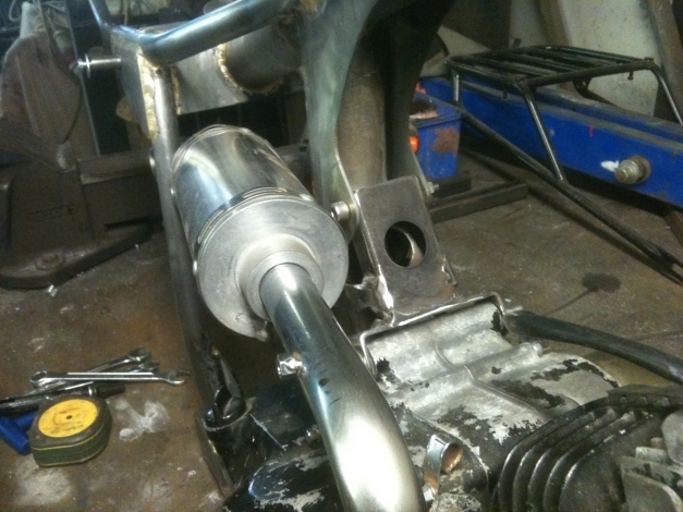
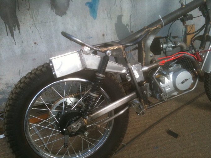
So today after a bitter disappointed at the MGP 2017, Stuart having engine problems in the first race... I went to work and fitted the "Lifan" engine back into the frame to find where the exhaust mounting should be.
I made New stainless steel bottom engine mounting brackets, and then had trouble lining up the new head steady mounting, but this problem was solved with two new holes being drilled, and a bit of adjustment work.
I finished welding the top engine mounting, and fitted the engine sump plate and frame, after again having to sort the bolt holes.
I just don't like forcing bolts into holes, I expect them to be easy to fit.
I am beginning to like this little bike just like the last one, and also have taken a liking for the engine, and now need to know what it performs like, do I keep it in this frame or build another?
We will see how we get on tomorrow...
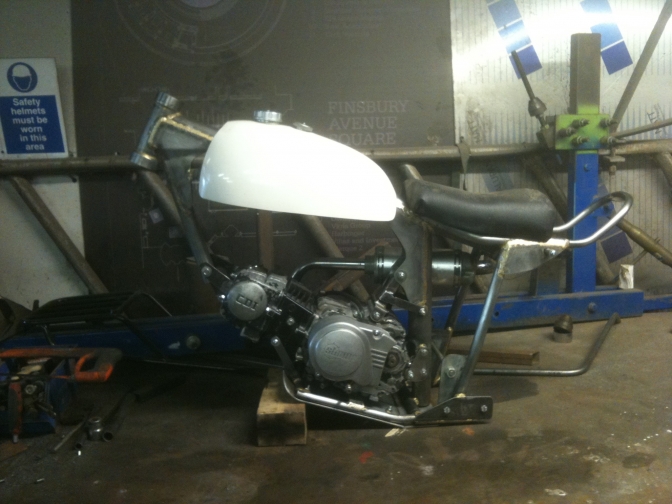
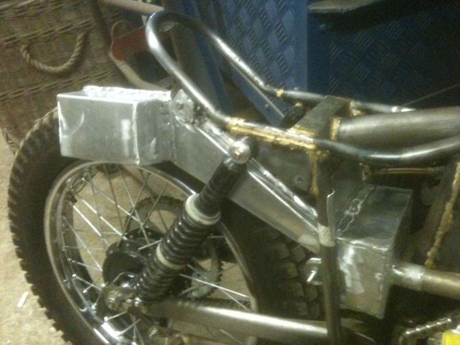
Well we have got on well today, and I have finished the tank and seat mountings.
I have also fitted a bracket to take the ignition coil, just in front of the tank, so that it is in the dry zone but is still kept cool.
The 125 Lifan motor I am keeping, and I have sorted a new gasket set, and service kit for the engine.
So It looks like the New YX 140 motor for this build.
I am liking this project more every day.
Blue by Friday.
07/10/2017.
Well after a weeks delay on the frame build, because of the "Horse Of The Year Show" work, I have been back on it this week, and made all the parts, and new jig bits for the swinging arm. And finally welded it up on Thursday.
It had taken three four hour sessions to get the swinging arm the way I wanted it.
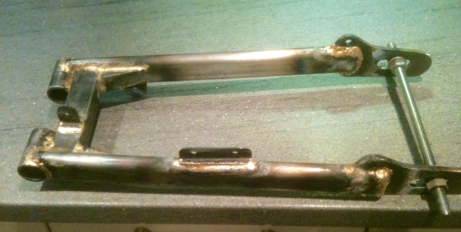
Has you can see I have altered this arm to the one fitted to the first Mini- Otter I have gone back to the "Mike Mill's" type layout, and I am using Metalastic bushes the same as used on Honda"s, and some Pit bikes.
There was nothing wrong with the one fitted to "Mini-Otter" Super-Cub "One" which was fitted with turned up Nylon top hat bushes, and we will go back to that system.
But just a case of knowing I have to use these Metalastic bushes on the Foster Otter builds, and thought it a way of trying them out on
"Mini-Otter" Two...
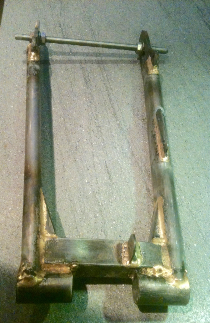
The threaded bar was fitted when I took the arm out of the jig, and tensioned inwards as the arm sprung outwards as it was removed,
It seems to have worked, because after finishing welding the under side, and releasing the tension it has sprung back into the correct width 7".
Yes I have got to run the right hand taking weld in on the bush carrier.
The heat was dissipated into my solid jig and made the joint a job to weld with a number 5 jet.
I think if anymore "Mini-Otters"® are built by us, I will Mig, or Tig weld the swinging arm assembly, or a mixture of bronze and tig...
I have dressed the bush holders ready to press in the bushes after paint.
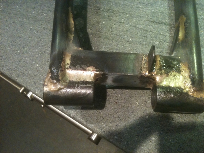
Re-welded joints with number 10 jet fitted.
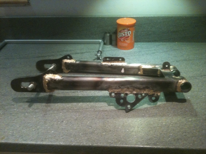
And then I welded on a side stand pivot bracket, Ahh Bisto.
More tomorrow.
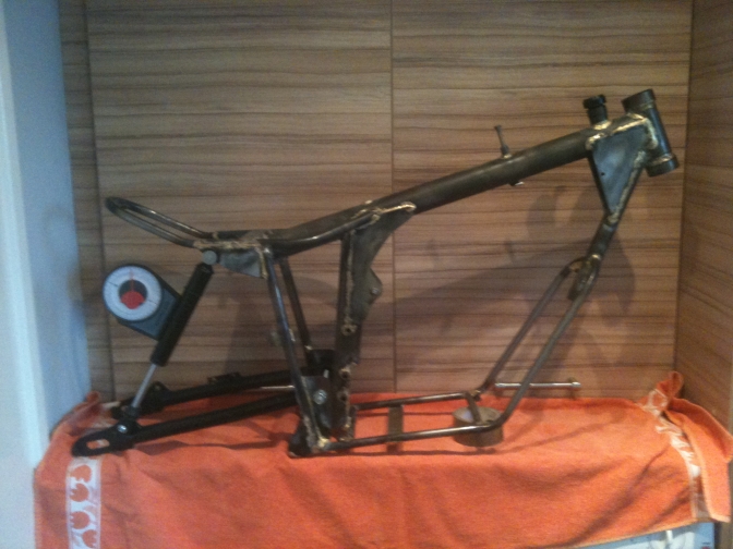
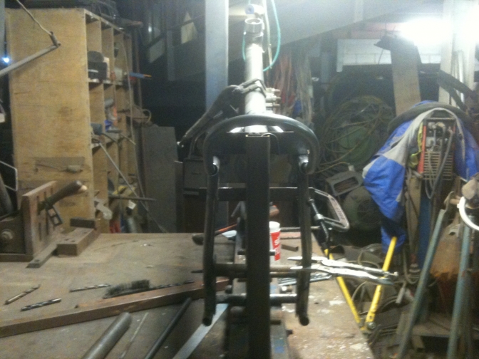
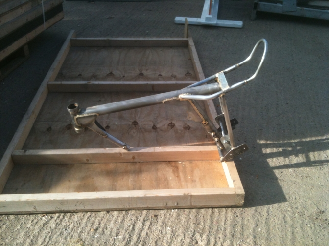
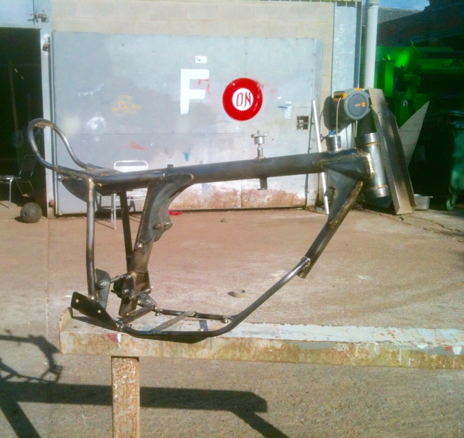
This is the frame you should end up with.
The steering head is the same as I use on all of my frames and the same dimensions as the Faber frames, this takes the L44643/10 tapered bearings used with the 1" stem spacers on the 3/4" stem of the BSA/Triumph "FourStud" forks.
Sitting below this is the filler Cap and neck. NOT for oil in this frame but for the fuel. This little machine will be running on the Aspen 4T fuel, and the Glass-Fibre tank that will be made fuel proof will be made from standard polyester resin.
Filler cap details below, a breather pipe will be incorporated into the neck.
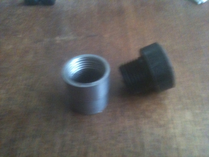
This cap I machined from Black Nylon, but you could use a 1/2"or 1" BSP brass filter cap and the appropriate black steel socket jointing tube if that is all you can get without the use of a lathe to turn this up.
I am going to stick with the YX 140 motor unit for this bike too.
We know the motor works very well in the first Mini-Otter, and we also now know how to tune it to our liking, carrying out the modifications we have now done on Mini-Otter One... Here it is in its delivery box.
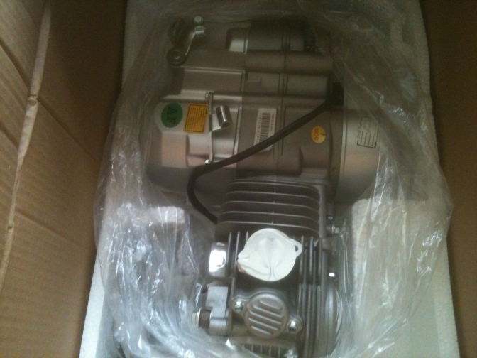
Mini-Otter Two's new engine...
_______
Back to 2015 for this bit...
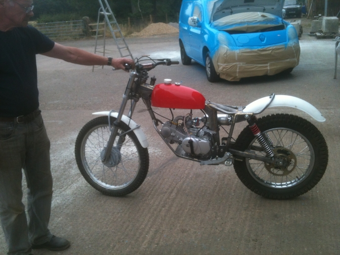
Brian Bedford has been over for ten days in July 2015 and with the picture of a Seeley Honda and some data from a friend of mine about exhaust dimensions...
He came up with a new exhaust for this project,
We were waiting for a new front pipe to be delivered, but it failed to turn up, so has Brian had to return to the Isle-Of-Man, I had to cobble up a front pipe to see how the New exhaust performed, on number one..
Well brilliant is the answer, quiet like a Honda 4RT and with a smoother delivery of power,
the job looks good for the future, and the system only needs tidying.
The cobbled up part is in Red.
We only fitted the parts onto the Mini-Otter One that were needed to ride it for a trial run and this is it...2015
The bike had been stripped down ready to paint the frame, so an hasty rebuild with the necessary parts to get it mobile were used.
The welding will be tided up with a Tig welder, we only had a Mig to weld it and it was a bit hot.
I will create the front pipe out of 29mm Stainless tube.
More on the build has we progress.
_______
2017...
This Now New page will just be about this second "Mini-Otter" Super-Cub,Two build. And there could be another on the way?
Here is the Jerred Honda frame as a comparison to how close the "Mini-Otter" Super-Cub, frames turned out looking the same and I have only recently had this frame photo as you know. July 2018.
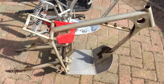
Photo Courtesy Alan J ©
"Mini-Otter"® SuperCub, trials machine specification.
Frame, Mainly built of T45 seamless tubing with exception of the rear frame mudguard loop, and engine under-run rails that are mild-steel 16 gauge ERW tubing.
Forks, are 1971 type BSA/Triumph so named Four-stud forks. The other alternative is Yamaha TY or Gas-Gas. 38mm forks.
Front Wheel, SH Yamaha TY 175 or New Honda C90 Cub hub and new stainless or alloy rim.
Rear Wheel, Jialing JH125L, or copies of the same, Steel WM3 rim.
Tank (Cover), Ray Small type glass-fibre polyester tank, or air-box modified version.
Tyres ,What are available at the time.
Engine unit, as standard, YX140, or Zongchen 145, at slightly greater cost.
Guards Gonelli plastic (White) or grey alternative.
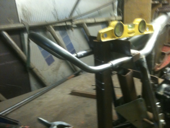
Bar's, Renthall 7/8" standard trials. 6" rise...
Levers ,Universal type.
Footrests, Universal type.
~~~~~~~
The specification may change, after more development.
~~~~~~~
14/08/2018.
Well "Mini-Otter Number Two" is finished and gone to the Isle Of Man with Mini-Otter Number One, so that Brian can get it running correctly, and test the little bike, he will then register it in the IOM as a Mini-Otter.
Photo's below.
The frame now has detachable under-run rails to the frame.
I tied with the idea of making the cylinder head bolts the front engine fixing, and then carried out the operation on the S/H Lifan engine while it was in the frame, but the frame sat in my conservatory from last autumn until now August 2018, and the more I looked at the system the more I disliked it.
So With the Brackley Bike Show coming up, and Brian Bedford over from the IOM, for the festival...
I said I would make an effort to get Mini-Otter "Number Two" finished.
I had most of the parts by now, and had to make another tank cover for the first Mini-Otter to cover the new air-box Brian was constructing, so I could use the tank from that bike on number two.
The weekend before the one Brian was meant to arrive, I took the new engine and frame to the workshop, and over the two days got the new under-run frame and skid plate fitted along with the footrests, purchased from Mick Ash as usual.
During the rest of that week I fitted the bushes into the swinging arm, with the aid of a blow-lamp, to warm the arm before pulling the metalastic bushes in with a puller, constructed of 10mm threaded bar and large washers.
The new tank cover was moulded, along with a tank base that was part of the new construction.
A new Jialing rear wheel came from stock, and two new wheel spacers to Brian's specification were turned up on the lathe.
I built up a pair of Triumph/BSA Four-stud forks from my dwindling stock, and just managed to find all of the parts necessary. I have to start buying again to replace what I used.
A Yamaha TY 175 front wheel was also taken from the stores, along with the newly shod brake plate.
I then realised I was short of a front mudguard bracket so used the Triumph Adventurer pattern I had to construct one of these, I would have bought one from Feked/Offroad, but thought I may not get it in time.
So Monday Morning before the Brackley Festival at the next weekend Brian was due to arrive, but the journey from the ferry at Liverpool and down the infamous M6, meant that it would be Tuesday before he could weald his tin-snips and riveter, for the air-box construction.
I basically spent the day sorting him, so it was not until Wednesday that I got to start assembling "Mini-Otter" Number Two.
More later.
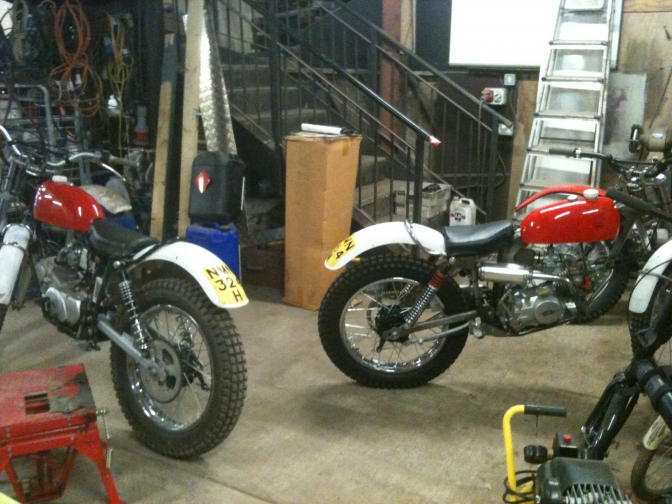
Mini-Otter No2 Ready for Brackley show...
No time for paint...
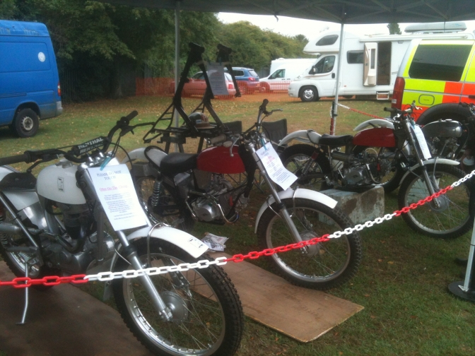
And on the BSA Otter stand with the other Otter Bikes.
Write up of finishing the build later...
15/04/2019...
"Mini-Otter Two" is now back from the Isle Of Man for a while...
The little bike was finished by Brian over there and then register as the second official Mini-Otter© of the brand...
While he was over here again from the Isle-Of-Man... Brian fitted a larger ignition flywheel to bike one, and the extra weight seemed to make a difference to how the engine ran..
So I ordered the same size alternator for number two.
Brian fitted the one on to Number one in ten minutes...
But it was a different story on the second engine.
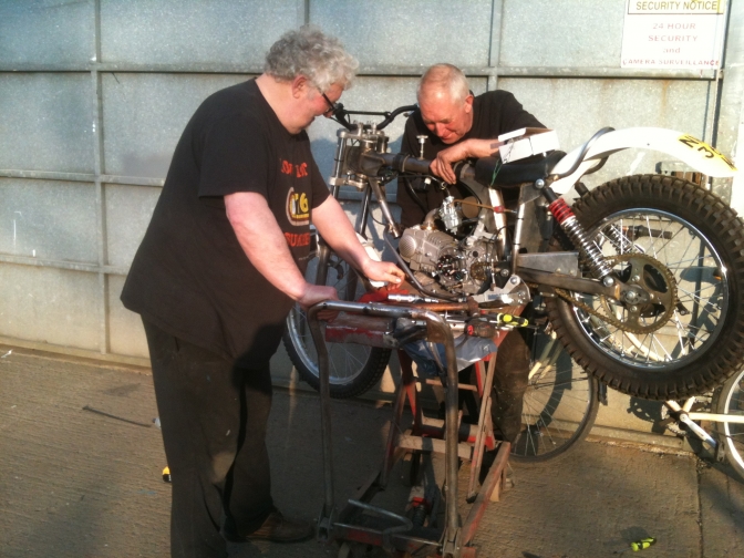
With the bike on the pump up stand the cover was quickly removed.. and a 14 mm spanner readied to undo the flywheel retaining nut, It would not budge...
I then spent half an hour making a flywheel holding tool, two in-fact, and ropped my brother, and Alan Smith, in to give me a hand .
Don't forget the ten minuets Brian had taken..
With a large power bar now attached to the socket we must have success! Not a bit of it, it bent the holding tool and the three foot bar was bending, they say these flywheel shafts sometimes break... Your joking...
Us Prescott's don't give up, and this nut was coming off.
"Fetch the 3/4" rattler" my brother said to Alan, the one used on truck wheel nuts..
Meanwhile brother manufactured a socket drive by welding the 14mm into a three quarter drive socket.
I could not bare to look because this tool was a brute...
A couple of rat-tat-tats and then that wherring noise that you hope for, the nut was off.
The next problem was the two cross head screws that retained the alternator backplate.. These would not budge either and broke a cross head socket that was guaranteed for life, and meant a trip to Halfords to replace it. Screwdrivers with grips attached were tried, with no result. I said I had an impact driver but this would need an overhaul to work... Another half hour.
Brother got out the lump hammer and we found a socket with the right cross section.. After lumping into the engine for what seemed like hours the first one moved, and the same time with the second.
Success at last...
I fitted the new set up back on in five minuets but could not get a spark, at the plug, I think, Brian had pinched the new one from the motor, or was it me?
"You will come off"...
~~~~~~~
So more later. PS. Andrew brought his De-Walt impact driver down to my house for Number Three engine and we got the nut and screws out in two minuets but they were just has tight.
19/06/2023...
Well since the bike returning from the Isle-Of-Man in 2019 it has been sat in the store without being stripped and the frame painted... as not a lot was done in the Covid-years at the workshop... bike wise...
So I am just trying to catch up with the builds, and a slot has turned up that I can just find time to take the Mini-Otter Two apart and paint the frame and other parts along with the engine modifications still to do on Brian's list and even fit one of the new side stand kits...
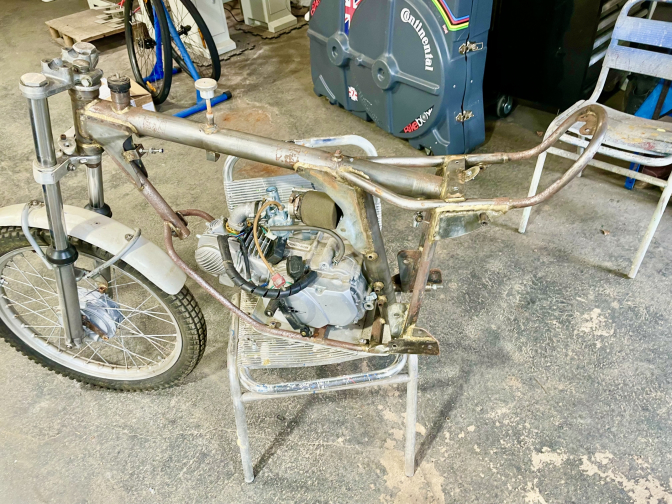
So we have a start with the bike now stripped down and the small frame parts in the media blast cabinet ...

Photo Courtesy "Otterman"...
Well that as taken a while but Mini-Otter 2 is now been painted and reassembled, and ready to ride again.. another little bike for the grand sons to get into trials with... worth the wait...
June 2024...
More on the build later.
Updat2023...06...
| Visitor Counter: | ||||||||
 |  |  |  |  | |  | ||