

The BSA C15 BOK 228C Replica.
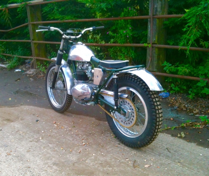
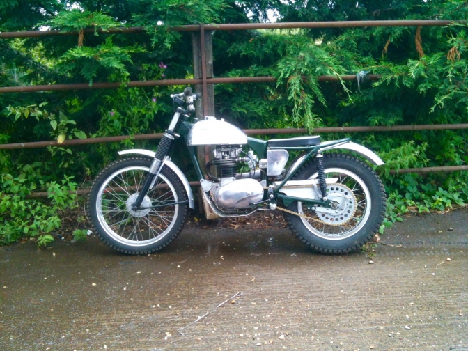
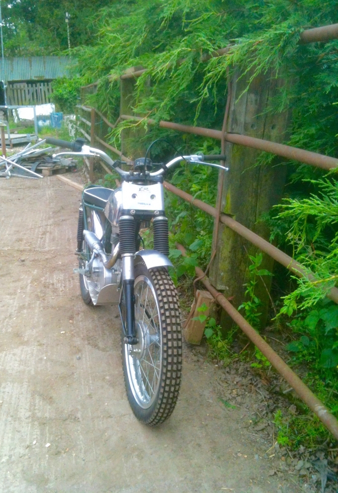
Nearly there... 17/08/2019... "Now that is better ". If you look at the photos below you will see the the air cleaner outlet was just too low for the carburettor. And instead of trying to modify the one fitted, I just made another with the outlet in the right place...
It has taken four hours to make this new air cleaner ... Where I could have bought one from Terry Weedy for £35... But the outlet would have had to been custom made..
Getting something to look right in your minds eye does not come cheap, or takes a lot of time.. I have found this out over the years... But I still very much enjoy what I do...
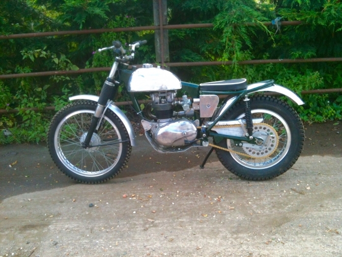
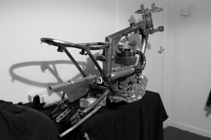
10/08/2019... Just got the Scott Ellis bike back out, after four weeks away building another frame and things. Still undecided about the carb after fitting it. There was a Mikuni on the Draper engine, so I thought right to keep one on it.(Or Copy)... But now I don't know? What ever I decide, I am going to make another air (filter) Box, same style but with the outlet more in line with the carb... This is has high as I can get it to fit nicely... I am sure I will find other things, like you do... But I am liking it and more every day... (Note New brake pedal)... ~~~~~~~ The project to build the replica Scott Ellis bike started way back in 2006...
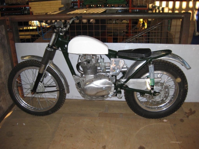
25/06/2019... Well that has been a long time coming..... But we have nearly got there in the end.. Should be finished next week.. Just waiting for the 520 rear sprocket from Amanda at Trialsbits. And need to fit a CDI-Coil for the PVL ignition.
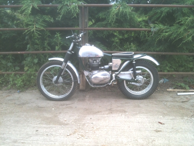
I decided to use the Nick Draper C15G engine that had been sat on a bench for eight years after I built it up. And I needed the "Hubbo" frame stripped back out to use as a pattern for a New frame jig. So what better engine to use than a engine used in a ex works BSA bike. And the bits inside are special as you may know. It will be nice to hear it run...
I made up a new D-type air filter for it, as the one fitted was the one Terry Weedy made me for a B25 engine with the carb angle coming out the other side of the seat tube. The seat that has been on the bike for years had been ruined by the use of a jet-wash to clean the bike last year, so the seat was sent off to a man who works for Brooks Saddles.. and he did a superb job of re covering my seat base with piped leather trim.. Too good for a trials bike really. The back brake plate retaining arm had another little works mod I was told about, and had a sliding mounting made.
The Scott Ellis Replica BOK228C has been stood about so long that fashion has changed since the little bike was started, the trend way back then was to have a wide sump protection plate, but now most are more sculptured and custom fitted. If you look at Scott's bike he tended not to use a sump shield at all. and therefore gain ground clearance without jacking the bike up, that was not done at the time. So I must decide whether to make a new plate up, or leave the one fitted?
More Later when we try and start the machine for the first time. Wonder what it will handle like?
~~~~~~~ My Take on the frame concept created by the father and son team Scott and Sep Ellis, That after being copied for being recognised as a potential winning machine, By four West country visionaries, when built up, and Named An Otter Product. Became the now Famous BSA "Otter"...
. And the vision that I decided was also the right move.
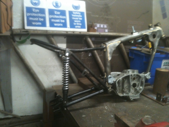
. You Have seen this frame of mine before, It has been used on other pages... But on this page you can follow "Now" the full build up of this machine over this winter 2017-18...
~~~~~~~
This is the New page for the long time build of my replica, the bike that started me on this journey.
I may use some of the old material that has been stored on my old computer since the build started a long time ago.
Why Now? Well If there is one bike that I must finish it has to be this bike, I am hoping to finish all of the bikes in build and more not yet started. But time starts to catch up with you in the end, and things slow down. Anyway the power unit for this bike, and that is all it really needs to complete the build, is now getting assembled.
OK... I have this week started to assemble the revised engine for the BOK128C replica bike. Revised as in I bought a better (As New) set of crankcases. These were C15D 1964 and last of the “Dizzy” motors. But I thought I had all the parts to convert this motor into C15 F spec. Well I must say I have got most of the parts but have been found wanting with a few, mostly silly little parts, like Woodruff Keys. A box full is now on its way. Any way the drive side case was shaved of two mm around the main-bearing oil-seal casting the bearing dropped in when heated and the new thinner oil-seal and spacer fitted. The timing side case was stripped of all parts left in the case. Oil pump, and drive shaft, and ball valves, etc. The oil pump was stripped checked refaced, rebuilt, and run up for smoothness. The cases were now heated and the main bearing bush and gearbox bearings gently drifted out. The cases were cleaned and then reheated so that the new gearbox and Alpha timing side conversion outer case fitted.
Time was spent making sure the correct tolerances on the main-shafts to bearings were right. (I am using the steel competition crank for this engine) I just like every thing to fit together without the need for any force. The Alpha inner bearing face and spacer was then gently pressed onto the shaft. The assembly then put together lightly bolted and checked for float and smoothness of movement. (Seems OK). I then started to collect from my stores the rest of the parts needed for the engine build, now we had a start with the bottom end, that looked and felt OK. An assortment of cylinder heads was checked through and the best selected, the one earmarked for this build was now discarded. After checking the valve stock I found I was short of the needed Alpha V169 inlet valve, Knowing there may be a wait from the factory I scoured the usual channels, and found that the valves are in short supply, even my normal supplier was out of stock, I eventually found one on e-Bay so that is now on the way, I then found this statement on the Alpha web site, so looks like some of my Phosphor bronze guides will be used. As I know of one case where the exhaust valve stuck in the guide of a bike and this probably caused the rider to miss out on a major trials win.
Statement below. From Alpha Bearings. Alpha Bearings supplies valves in either stainless steel (exhaust material) or in Nimonic 80. This makes certain that they are suited to the lead free fuels used today. Care should be taken when using a stainless steel valve in a cast iron valve guide. The application of either a valve with a suitable surface treatment or a phosphor bronze valve guide. Since the designation of the valve does not specify the application to the extent that it is always known that it will be used in a particular guide material the specific application is left to you. Should you wish to use a cast iron valve guide then please ask for the valve to be supplied with a hard chrome or nitrided stem? These treatments are only required on exhaust valves. In the same way any valves that are dimensionally the same as the corresponding exhaust valve will only be supplied in stainless exhaust material.
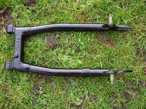
Here is the story of the build in 2007... Starting with The Way I bent the swinging Arm to make it 1 inch wider.
I will try and find the Part No of this swinging arm for you can't quite make it out here.
Well I have just recovered the files that I had written in 2006 for the start of this build so the story continues here. And by reading it you see how very little knowledge I had about the BSA "OTTER" name at that time. 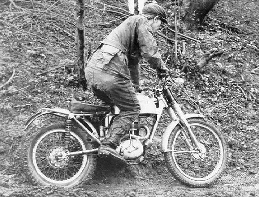
We can now see that BSA could have, if the right management had been in place at the time, built similar bikes to this Scott Ellis interpretation of what a Trials BSA for sale over the counter,should have been like, just by replacing the heavy scrambles frames that they decided to use “because they had them” with one on the same lines as the “comp shop” boys had already built.. The so called “Otter” frame could have been developed along side the works Bantam prototypes Red T 1, and 2, (standing for Redditch Trial one and two) but that’s another story...
So this is part one of the story. from 2005-6.
Most of the above knowledge as come to me while looking for the correct bit’s to put on, and into the replica I am now building. So we start with the main part of the bike and the part that gives it the name “Otter”, the frame. The first thing to do after some thought was to build a frame jig. So a few hours where spent trawling through page after page on the net looking for a pattern or at least a picture and some information of same, so that I had some idea how to start building one. I eventually found what I was looking for on, would you believe it an American eBay page that had the jigs for sale. The information they had posted about the jig was just what I wanted. Probably if it had been on eBay here in the UK I would have bought one, as I thought they were not too dear. A couple of evenings were spent perusing over the images and data I had printed off, trying to take in how this jig worked and what I needed to make a copy. The steel and bolts were ordered, and I set too turning the steel cones on my old lathe. A week end, and a few spare hours, saw the rudiments of the jig made. I had purchased an angle finder from eBay hoping it would arrive before the Christmas break, as I was anticipating starting the frame during this time. I ordered the appropriate lengths of T 45 tubing from just up the road in Birmingham and sent my brother off to pick the order up. Well during the Christmas period I managed to set the jig up ready for building the frame, with the help of the angle finder, and a Faber “Otter” frame that was ready to send of to the powder coaters in Redditch as this was stated to have the same angles and dimensions as Scott’s original frame. The two main frame tubes (seat and top) were cut and hand mitred, and then tacked together on a steel setting out bench. The head tube was cut and then machined on the lathe to the correct dimensions, also two bearing retainers made to braze into the tube. These were then mitred and fitted onto the jig ready for bronze welding. Next, a week was spent making and machining the various gussets, tubes, brackets etc, before welding the front half of the frame could begin. A weekend and a few hours that I found between other paying jobs accomplished the task. What I now needed was a Triumph Tiger Cub swinging arm and rear sub-frame. Hours during the next few weeks were spent trawling through eBay and other sites looking for one. Stupidly we had a Late Tiger Cub but only bought the bike for the engine and wheels for another project, and had put the rest of the bits back on eBay, and actually delivered the frame to a guy in Derbyshire on a journey to Sheffield the year before. Well in late February a frame came up for sale on eBay, I saved the picture and blew it up to see if I could estimate the condition of it. There was a lot of surface rust and I could see that the front engine mounting was broken but the sub frame didn’t look to bad, I hoped the damage might put off other viewers bidding, and the cost of posting the item was not cheap at £28. Abingdon was not that far away from me, so I had already decided if I won the item to pick it up. Well I got it for £40 and rang the person to see if we could pick it up the following week end, which he agreed. I got Lee to chauffeur me to Abingdon has I was still recovering from illness and did not want to drive because of the medication I was taking. What a journey; I have never met a thunder storm as bad, and in February when we should have been getting snow. We found the address and I dashed to the door, but still got soaked. A smartly dressed school teacher opened the door and was putting on his raincoat as he did so. “I’m due to be leaving in a couple of minutes” he said “or I would offer you a cup of tea”. “What a dreadful day”? Isn’t it . I handed him two soggy twenty pound notes and we collected the old frame from the back garden. I handed him the printed off page from eBay as conclusion of the deal, and we both left the house trying to shelter our heads from the torrential rain, his umbrella turning inside out within a few strides. I got even wetter trying to put the now wet and rusty frame, into Lee’s car without making a mess. When we got back home the first thing I did with the frame was soak the swinging arm pivot with the last of my cans of WD 40, then shut the door of the shed and left it for a day soaking. With good fitting spanners and appropriate sized drift I managed to persuade the pin out of the frame swing arm mounting and unbolt the sub frame. They were not in as poor a condition as I expected, the front loop was in the more deteriorated condition than the parts that I needed, and I thought I could even use that to set the jig for the next project. The next action was to clean the parts up ready for modification. What I needed to do was stretch the width of the sub frame an inch and the same with the right hand leg of the swinging arm. Not an easy task I can assure you. As I wanted to achieve this with out cutting either part.
This is one lengthened one inch by Ray Small. But the right hand leg is still straight, not the profile of the left hand leg as I was trying to achieve. ~~~~~~~
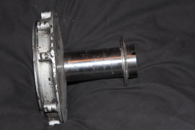
With the use of the gas bottles, cunning, and a little brute force, I managed to fulfil the challenge. But I don’t think that I would attempt it again, I would try a different method that would include the use of a welder. A further go at the sub frame with hydraulic machinery jack and gas welder was needed before it met my approval. I had managed to buy a late type BSA Bantam rear hub from eBay for the princely sum of £5.00, but the postage was £10, still cheap I thought as it was in really good condition, it was cleaned off and the bearings and spindle removed. Then I made up two machining bosses on the lathe and fixed these into the hub with threaded rod. The hub was then centred in the lathe and carefully parted in the middle. A line had been struck down the length of the hub beforehand with a straight edge and scriber as a guide to keeping the spoking right on reassembly. A new centre section was machined with spigots each side to fit into the two parts of the hub, leaving the raised middle section at one inch long. (If you use a Triumph Cub hub, this middle section needs to be longer by about half an inch as the Cub hubs are narrower, the finished hub should come out at about four inches across the spoke flanges.) The now three parts of the hub were pressed together, lining up the two scribed parts, and then, the now widened hub refitted into the lathe, and centred so that the hub ran true. The three parts were tacked around with the mig welder and then again checked for trueness, before finally welding the three parts together in the lathe, spinning the hub as welding progressed. This was then left to cool and again checked for accuracy, before machining along the length of the hub to make it once more smooth. The hub was then turned around and fitted in the jaws with the drum side out, and the brake surface skimmed. (The other alternative would have been to buy one of the alloy replica hubs that are on the market. But this would have not been cricket would it.)
This is the Rear Hub that was machined for the Replica bike. Photo Lee Prescott.
I then turned to the hub back plate for modification. It was a known fact then in the sixties as it is now, that none of the Bantam/Cub production back plates ever centred up between a line strung between the centre of the fulcrum, spindle hole, and pivot stud. And the back plate retaining fixture was very poorly designed, taking all the braking pressure through a slotted hole that was designed for brake adjustment. Constant braking pressure would undoubtedly bend the top part of the slotted plate loosening the fixing bolt, or worst still pulling it through the now bigger hole. Best way I have found for a cure or update is to drill out the rivets and spot-welds holding this section on to the backing plate, and throw it away. The brake pivot stud was driven out leaving a seven sixteenth of an inch hole. I them machined up a new pivot stud that was long enough to thread three eighths BSF for the new pivoting brake anchor plate. I then carefully lined up the three centres before brazing this new part into place. (Two birds with one stone you see). Cosmetically cleaning up the outer side by welding the holes and half drilling's that I had made, and then finished ready for painting with a linisher. A new floating brake anchor plate was made out of thirty (30mm) by five (5)millimetres stainless steel, and drilled for lightness. I made a triangular shaped plate for retaining this to the swing arm along with one of the same shape for holding the rear chain tensioner, and then bronze welded the two in the appropriate position on the swinging arm. I know these modifications were not strictly a copy of the Scott Ellis bike as I have no picture of this side of the bike. And only steel chain guides were used at the time. But if I, or someone else was going to ride this machine when it was finished, it seemed the sensible thing to do. I also made and fitted a plate and prop stand onto the opposite side of the swinging arm as this now seems to be semi-compulsory in the eyes of most trials scrutineers’. A pair of oversized brake shoes were purchased, and fitted to the refurbished back plate, and then skimmed on the lathe for accuracy. The hub and back plate were then painted with base coat and lacquer, along with the front hub that had been treated to a new fulcrum, and then the brake shoes were skimmed the same as the rear. When the painted hubs had been left to cure for a couple of days they were fitted with new fully sealed bearings, and the back with new longer spindle that I had machined. The front would be fitted with alloy spacers and new spindle to fit donor forks (WD BSA B40) later. Both hubs were now ready for Lee to lace up into the new Flanged alloy rims that were a copy of the ones used in 1965-66. More on the lacing up of the wheels later.
So the next obvious step to building the replica Works BSA was to find one of the very scarce C15 F type engines. I had been keeping an eye on eBay for one for some time but the only ones that came up seemed to be either earlier engines with the distributor or the later expensive G type engine with the revised oil pump and end fed crankshaft. I was determined to have the right engine for this project or what would be the point of the exercise. The collection of bikes that my brother and I have put together already had a C15T in it. The ex Brian Hyatt bike that had been featured on the front cover of one of the superb Offroad Review magazines. This bike has the correct “F” type motor but has been much modified inside and out and there was no way that we could cannibalise this bike for the engine, as it has nearly has the same amount of history has the Scott Ellis bike.
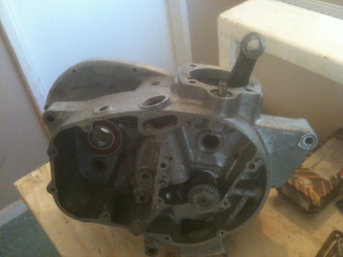
Well in mid February 2007 the crankcases for an F type engine appeared on e-bay. I instantly saved the picture of the engine to my computer and blew the image up to get a better look at the lump. It did not look that good; in fact it looked as if it had spent a considerable amount of time since 1965 under a hedgerow, or at least in a damp shed. But this was a chance to get my hands on a genuine BSA engine that even had an “F” behind the engine number stamped on the crankcase. I watched eBay like a hawk for the next seven days, and the stress was getting worse day by day; the night before the finishing time of the auction for the crankcases I could not get to sleep at all, even after drinking a full bottle of red wine. (Sad). In the morning I rang my brother to tell him I would not be in for work as I was suffering one of my number one head aches, and it was true. With one hour to go before the finishing time of the said item, I cranked up my old computer. It usually took one or two attempts, shutting it back down and starting again before the broadband would kick in, and this time was no exception. Once I had got her running and had signed on to my eBay, I was nearly to nervous to look and see if I was still highest bidder on the engine. I was, and every minute in the remaining hour seemed like a week. By the time the last few minutes came, my hands were shaking that bad that there was no way that I could have punched in another bid. It was as much has I could do to keep hitting the refresh button. It seemed like the auction was never going to end, and I could hardly believe it when “you have won this item” came up. I knew I had got to pay for the item with my credit card has the seller had no Pay Pal facility. I hit the pay now button within seconds of the action finishing, wrote down the seller’s phone number and quickly rang it. The guy on the end of the phone was shocked and did not know the auction had ended, I had to tell him how much the crankcases had made, then he could not find a pen to write the card number down and had to run off to find one. I hope he does not think the price of £20.00 was too cheap for the cases I thought to my self as I waited for him to come back to the phone. He took down the number of the card and said that he would put the cases onto there carriers van that afternoon. A knock at the door at seven o’clock the next morning woke me up with a jolt; I got to the door and opened it to a guy rubbing his hands together to get some feeling back in to them, it was a sharp frost that night. He gave me a paper invoice from Villiers Service Wolverhampton, with the card receipt stapled to it; “I’ve got a big plastic box for you” he said and ran off down the car park to get it. The plastic bin the cases came in was probably worth more money than the bits inside. But not to me. Anyway this is the lump below as it arrived.
Photo here when retrieved from old computer.
After drinking my tea and eating my toast, I unwrapped the parcel to see what treasures were hiding inside. From looking down from the top the cases didn’t look has bad as I expected, but turning it upside down I could see I was right about the damp shed, as there was a fair bit of alloy corrosion. The rest of the morning was spent for a start, gently removing the stubborn rusted Allen set screws from the timing cover and chain case. They eventually all came out without disaster, revealing more parts than I expected. There was a gearbox mainshaft, complete except for the second sliding gear, and they were still covered with old dried on oil that had kept them rust free. Removing the timing inner cover also revealed an oil pump in the same condition courtesy of the old oil again. As you can see from the picture there was also the gear selector and a cam-plate also in a serviceable condition. The studs from the rusted through sump cover were again gently removed, and then the oil pump, this still reluctantly could be turned so was set aside for strip down later in the day on the kitchen table. The crankcases were eventually persuaded to come apart revealing no major faults, and unbelievably clean. Each side were heated gently on the old gas cooker in the back kitchen and the rest of the studs removed with the help of my trusty sliding Mole grips. I was well pleased with the result of the mornings work, and after lunch the oil pump was striped ,cleaned and the gears lapped in with a small amount of T-cut before oiling and reassembly I thought the entire day had been a good result. The next day I took the cases to work at my brothers, and found time to sand blast them during the day, on closer inspection after they were blasted showed that the corrosion was not has bad as I thought. And after a jolly good polishing with industrial polishing machine that we had bought from Massey Ferguson factory when they closed, converted both outer cases to more than usable objects, and me into looking more like a nineteen fifties chimney sweep. I now had two cases that I could fit together and place in position in the frame, so that I could make templates for the alloy mounting plates.
I could not find a picture of Scott’s bike that was good enough to show how he had mounted his engine in to the frame. But it was sensible I thought to use Dural engine plates as the engine could then be aligned in all directions with the use of alloy spacers, that I now loved making on the old lathe.(how had I managed before without this piece of machinery I don’t know). I left the frame in the jig while I made these plates, because I thought then I would have half a chance of getting every part in-line. I had welded four through tubes into the frame at the bottom of the seat tube and the front down tube in the appropriate place to take the back and front engine mountings. Cardboard templates were made and tried in position, then reshaped several times until the shape of them pleased me, and that they were strong enough to do the job they were designed to do. The shape was then transferred onto the five millimetre Dural plate and then cut roughly out on the band saw. (Another old piece of machinery that I could now not do without.) The rough shapes were linished to the correct shape before I measured out the holes to be drilled correctly, checking them several times. Before actually drilling them. The two plates were then bolted to the frame and the engine slid into place, roughly lining up the chain line, showed that I needed a spacer ¾" of an inch on the right side of the frame at the back and one of 3/8" of an inch on the left side. The front was opposite and needed two spacers ½ inch wide on the left hand side. So these I turned on the lathe out of aluminium. This was a rough starting point for the way the engine would sit in the frame and any minor adjustments could be made with stainless steel shims nearer completion. I could now design and make up a head steady bracket that was to be the third major fixing point for the engine, the one that would give the rigidity to the engine to frame mountings. The bottom mounting on the engine would be fixed to the aluminium skid plate which is to be fixed to the back and front main frame members to, not only to protect the engine, but to act as a added stabilizer between the main tubes. The head, barrel, and rocker cover, were fitted loosely to the crankcases to work out the position of the top mount. I then needed to add on ¼" of an inch to this measurement as I would later make a spacer this size to fit to the bottom of the barrel as I was using a alloy one from a BSA B25, (I only thought of using this as I had found a photograph of “BOK”228C then with the modified production frame but fitted with an alloy barrelled engine) and this is the distance you have to make up to be the same height as the iron BSA C15 barrel. Again card was used as a template for this before the outline of the two pieces needed were transferred to the stainless steel that I was using. This is the out come below.
~~~~~~~ For the next six months hardly anything was done to the project, except trawl through eBay on a daily basis trying to locate, and then buy the rest of the missing parts for the engine and gear box. One week there would be no parts at all, on my large list, and then three or four would come along at once, creating a situation not unlike the Lottery, which one should you choose? Some parts were won, some were lost. And some unnecessary parts were bought, because they seemed cheap at the time and could be used for later projects. Two B25/TR25 cylinder heads and three B25/TR25 rocker covers were bought, just in case I changed my mind later and decided to fit one in place of the correct C15 head and three rocker covers, that I had purchased from various parts of the country. One bargain I managed to win was a new MK1 Amal concentric carburettor the correct one for the engine a 622, and a replacement for the original Monoblock that was fitted in 1965, and twenty pound less than I could buy one from the manufactures. And then along came a steel crank assembly with the biggest roller bearing connecting rod bigend fitted and specifically for the “F” type engine. I had to make two stabs at getting the correct crankshaft timing pinion, the first one turned out to be for a later engine with the smaller shaft hole. I was in two minds to get my old mate Paul Ellis... to enlarge the hole and re-cut the key-way, but just in time the correct one turned up, with its big brother the cam shaft pinion for the same money, five pounds, the same amount I had paid for the one that was wrong. I had already bought a camshaft and followers along with the large pinion, from a chap that I had got to know very well on eBay, Ken O’Brien from Oxford, he had supplied me with various bits from a cylinder barrel, to gear selector forks and other small parts for this bike and others. Now you might say, so why didn’t you buy all these parts at once from the bloke. Well if I was using eBay as a Lottery, Ken was using his shed as a Lucky Dip, and only put parts on to the auction site when he got to them. So it was a waiting game, but made life interesting every Saturday to see what the bloke had come up with that week. I know it’s sad, and I should get a life: But you tell me where you could get parts for this forty five year old project if it was not for this web site. There may be parts that could be unearthed and would do the job three or four doors down from where I live , but you would not know would you, unless they were put on to this eBay site to be sold. By this time my machining abilities had improved somewhat, so the parts for the bike that were easier to make than to find were made. Several pairs of back wheel nuts were made, with the new technique of threading them straight by fitting the tap in the tail-stock of the lathe, and then spinning the chuck with the drilled nut in by hand, still frightened of running the power of the lathe as the tap was an outrageous price and I am still in the state of learning to screwcut on this lathe. 2008... 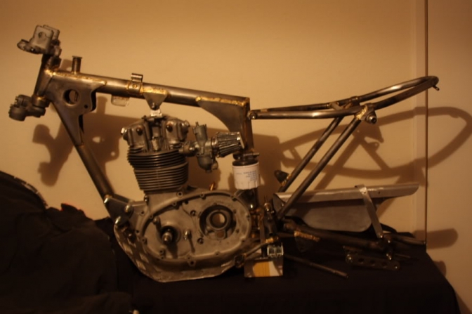 More Later. |

05/10/2018.
Well its been a while again.
But every time I go to get this bike finished another project pops up. But I have left the bike in the bottom workshop so it is in my way, and I keep falling over the rolling chassis, everyday, so I have a look and give it a quick dust off and spin the front wheel as it is on its stand-lift.
Then along came the OC project. (Otter-Cheaper.)
Well it is basically a brother bike to the Scott Ellis Replica.
So a lot of the reference points from this bike were used, like the engine mounting plates and the subframe bends etc.
The engine for both bikes are sat on the bench in the engine room, and both just need the cylinder heads fitted and a choice made to which ignition system to use on either machine.
I should keep the Scott Ellis bike on Energy transfer, or better still the Lucas Rita ignition used at the time, but I may go for a simple coil ignition running on total loss, now the batteries are available.
So hopefully we will come to a conclusion on both of these builds.
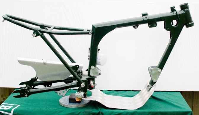
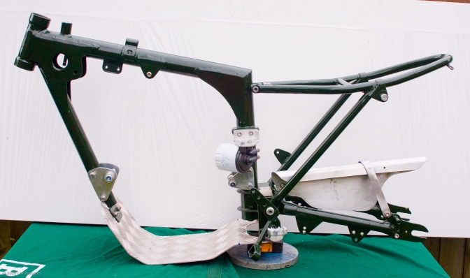
This is the Otter Cheaper OC project frame. Off to the powder-coaters this next week. Oct 2018...
More later on the progress of both.
Updt2023...05...
| Visitor Counter: | ||||||||
 |  |  |  |  | | | ||